Manipulator tail end and method based on intelligent sensing of ultrasonic surface wave contact stress

A technology of ultrasonic surface wave and contact stress, which is applied in the directions of manipulators, measuring force, force/torque/work measuring instruments, etc., which can solve problems such as high cost, limited strength, and inability to reflect local stress conditions at the end of the manipulator and the contact part of the object.

Pending Publication Date: 2021-02-26
CHINA UNIV OF MINING & TECH
View PDF0 Cites 0 Cited by
  • Summary
  • Abstract
  • Description
  • Claims
  • Application Information

AI Technical Summary

Problems solved by technology

[0004] The strain gauge force sensor on the manipulator can be used to measure the clamping force or torque when the manipulator clamps the object, but the local stress condition at the contact point between the end of the manipulator and the object cannot reflect
Although the bionic skin of the robot has various tactile functions such as touch, pressure, and slip, it has problems such as limited strength, complicated manufacturing process, and high cost.

Method used


Image

  • Manipulator tail end and method based on intelligent sensing of ultrasonic surface wave contact stress
  • Manipulator tail end and method based on intelligent sensing of ultrasonic surface wave contact stress
  • Manipulator tail end and method based on intelligent sensing of ultrasonic surface wave contact stress

Examples


Embodiment Construction

[0061]The present invention will be further explained below in conjunction with the drawings:

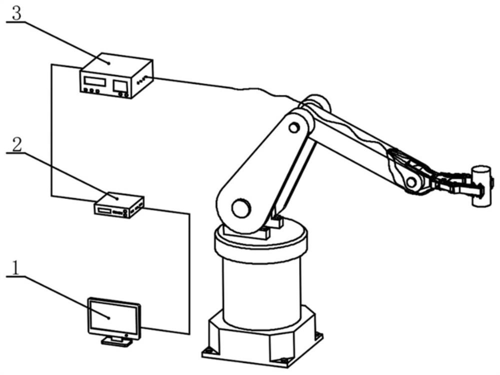
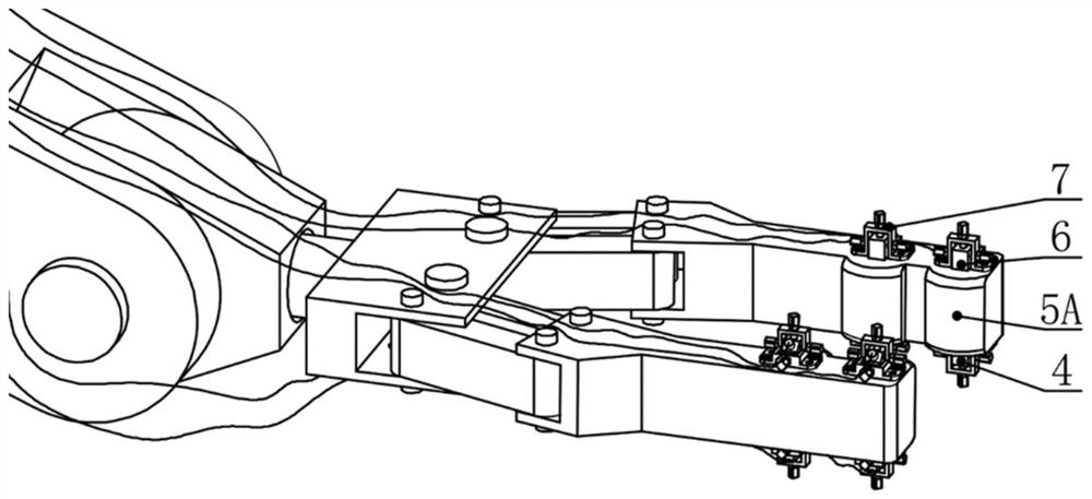
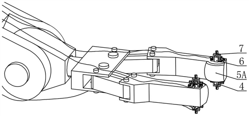
[0062]Such asfigure 1 As shown, the end of a manipulator based on the intelligent sensing of ultrasonic surface wave contact stress of the present invention mainly includes a computer 1, a data acquisition card 2, and an ultrasonic transmitter receiver 3 connected in sequence; the ultrasonic transmitter probe 4 and the ultrasonic receiver probe 6 are both Connect to the ultrasonic transmitter receiver 3 interface; the manipulator must use a special cylindrical end 5A or a spherical end 5B; a probe holder 7 is installed on the finger end side plane to adjust and fix the position of the probe on the upper and lower planes of the end.

[0063]The end of the manipulator based on the intelligent sensing of ultrasonic surface wave contact stress is characterized in that it includes a pair of matching mechanical fingers as a clamping mechanism. The front end of the mechanical fingers is a cylindrical ...


PUM


Abstract

The invention relates to a manipulator tail end and method based on intelligent sensing of ultrasonic surface wave contact stress. The manipulator tail end and method are suitable for real-time monitoring of local contact stress of the tail end when an industrial manipulator grabs an object. The manipulator tail end comprises a specially-made manipulator columnar or spherical tail end, an ultrasonic transmitting and receiving probe, probe supports, adjusting bolts and nuts, an ultrasonic transmitting and receiving device, a data acquisition card and a computer. The probe supports are installedon the upper plane and the lower plane of the manipulator tail end, and the adjusting bolts and nuts on the probe supports are used for adjusting and fixing the position of the probe. The probe, theultrasonic transmitting and receiving device, the data acquisition card and the computer are sequentially connected. During work, the ultrasonic transmitting and receiving device sends out an electricsignal to stimulate the ultrasonic transmitting probe to generate surface waves; the surface waves are transmitted along the surface of the manipulator tail end, and the receiving probe receives thesurface waves, converts the surface waves into an electric signal and transmits the electric signal back to the ultrasonic transmitting and receiving device; and the data acquisition card samples anddigitizes the sent and received signals, by the computer, data storage and calculation analysis are achieved to obtain change of the surface wave transmission time, real-time monitoring of the local contact stress of the manipulator tail end is achieved, and the industrial manipulator which is cold originally has the capacity of sensing the contact stress.

Description

Technical field[0001]The invention relates to a manipulator end and method, in particular to a manipulator end and method based on the intelligent perception of ultrasonic surface wave contact stress for industrial manipulators.Background technique[0002]The manipulator is a new type of device developed in the process of mechanization and automation. It can imitate certain movements of the human arm to grab or carry objects. It has the advantages of both human and machine in structure and performance. With the development of robot architecture, the flexibility, accuracy and speed of the manipulator can be compared or even surpassed by the human hand, but the cold manipulator does not have the tactile sense like the human hand. How to make the manipulator have the tactile sense like the human hand and become a robotic hand Hot issues in the field.[0003]When a human hand grasps an object of a specific shape and material, it is necessary to consider whether the force between the finger ...

Claims


Application Information

Patent Timeline
Patent Type & Authority Applications(China)
IPC IPC(8): B25J13/08G01L5/00G01L1/25
CPCB25J13/085G01L1/255G01L5/009
Inventor 胡而已卢精文孙鸿兵
Owner CHINA UNIV OF MINING & TECH
Why Eureka
Try Eureka