
Temperature-controllable self-positioning bar hot rolling transportation roller way

A technology of conveying rollers and positioning rods, which is applied in the field of metal pressure processing, and can solve problems such as indentation, bar surface scratches, damage, etc., and achieve the effects of prolonging service life, reducing uneven wear, and improving yield

Pending Publication Date: 2021-07-23
SHANDONG IRON & STEEL CO LTD
View PDF1 Cites 0 Cited by
  • Summary
  • Abstract
  • Description
  • Claims
  • Application Information

AI Technical Summary

Problems solved by technology

However, in this patent, since the surface of the roller table is flat and its cooling method is air cooling, damage will inevitably occur. When the surface of the roller table is severely worn, it is easy to cause quality problems such as scratches and indentations on the surface of the bar.

Method used


Image

  • Temperature-controllable self-positioning bar hot rolling transportation roller way

Examples


Embodiment 1

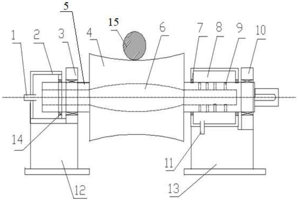
[0023] Such as figure 1 As shown, a temperature-controllable self-positioning bar hot-rolled transport roller table, the transport roller table includes a water inlet pipe 1, a water inlet tank 2, a fixed end bearing housing 3, a roller table 4, a roller table shaft 5, and a cooling pipe Road 6, water outlet tank sealing ring 7, water outlet tank 8, drain hole 9, transmission end bearing housing 10, drain pipe 11, fixed end base 12, transmission end base 13, water inlet tank sealing ring 14;

[0024] The water inlet tank 2 and the fixed end bearing seat 3 are arranged on the fixed end base 12, and the water outlet tank 8 and the transmission end bearing seat 10 are arranged on the transmission end base 13;

[0025] The surface of the roller table 4 is a concave arc-shaped surface, the roller table shaft 5 passes through the center of the roller table 4, and the inside of the roller table shaft 5 is provided with a cooling pipeline 6; one end of the roller table shaft 5 passes ...


PUM


Abstract

The invention relates to the field of metal pressure machining, in particular to a temperature-controllable self-positioning bar hot rolling transportation roller way. The temperature-controllable self-positioning bar hot rolling transportation roller way comprises a water inlet pipe, a water inlet tank, a water tank sealing ring, a fixed end bearing seat, a V-shaped roller way, a water outlet tank, a water drainage pipe, a transmission end bearing seat, a cooling pipeline, water drainage holes and a base, wherein the water inlet tank and the fixed end bearing seat are installed at the non-transmission end of the roller way and fixed to the base, the water inlet pipe is installed on the water inlet tank, and the water inlet tank and the roller way end are assembled in a sealed mode; and the roller way surface is sunken. The water outlet tank and the transmission end bearing seat are installed at the roller way transmission end and fixed to the base, the water drainage pipe is installed on the water outlet tank, the water drainage holes are formed in the roller way transmission end, and are sealed in the water outlet tank; and due to the fact that the inclination angle exists in the roller way surface, bars are automatically centered to a center area of the roller way surface in the conveying process, the bars are prevented from touching the two sides of the roller way, and uneven abrasion to the roller way surface is reduced.

Description

technical field [0001] The invention relates to the field of metal pressure processing, in particular to a longitudinal conveying device for a hot-rolled bar production line, and more specifically to a conveying roller table device for the bar in the rolling process. Background technique [0002] The roller table is the main equipment for longitudinally conveying the rolled pieces in the steel rolling production line. The rolled pieces enter and exit the heating furnace, are rolled by each stand and then transported to the rear for collection and finishing. All are completed by the roller table, and the length of the roller table runs through the entire Rolling production line, therefore, the weight of the roller table equipment is relatively large, accounting for about 40% of the rolling equipment. Because it bears the important role of connecting the previous and the next, the quality of the roller table such as wear resistance, impact resistance, and service life has an i...

Claims


Application Information

Patent Timeline
Patent Type & Authority Applications(China)
IPC IPC(8): B21B39/02B21B39/14B21B39/34B21B45/02
CPCB21B39/02B21B39/14B21B39/34B21B45/0224
Inventor 王宗斌梁娜陈良李浩秋许京铭尹崇丽马丙涛石军强王允郭磊李毅
Owner SHANDONG IRON & STEEL CO LTD
Learn More