New material stirring device capable of effectively preventing too high stirring speed

A stirring speed and stirring device technology, which is applied in the direction of mixer accessories, transportation and packaging, chemical/physical processes, etc., can solve the problems of reducing the practicality of stirring devices, waste of new materials, and affecting the performance of new materials, so as to improve the practicality And the effect of timeliness, guaranteed performance, and avoiding excessive stirring speed

Inactive Publication Date: 2021-07-23
泗县米和花新材料科技有限公司
View PDF0 Cites 0 Cited by
  • Summary
  • Abstract
  • Description
  • Claims
  • Application Information

AI Technical Summary

Problems solved by technology

[0002] New materials are a new type of material that we often use in our modern life. The current new materials are mainly for energy saving and environmental protection, so the production process will be more complicated than traditional materials. For example, some new materials are in the production During the process, it is often necessary to use a stirring device for sufficient stirring, but when the current stirring device is used, some problems often occur, which affect the performance of the new material
[0003] During the stirring process of the current new materials, not only need to stir fully, but also pay attention to the stirring speed. Once the stirring speed is greater than a certain value, the performance of the new material may be destroyed, resulting in the failure of the original performance of the new material, greatly Reduce the practicability of the stirring device, and also cause waste of new materials, the loss outweighs the gain

Method used


Image

  • New material stirring device capable of effectively preventing too high stirring speed
  • New material stirring device capable of effectively preventing too high stirring speed
  • New material stirring device capable of effectively preventing too high stirring speed

Examples


Embodiment Construction

[0019] The following will clearly and completely describe the technical solutions in the embodiments of the present invention with reference to the accompanying drawings in the embodiments of the present invention. Obviously, the described embodiments are only some, not all, embodiments of the present invention. Based on the embodiments of the present invention, all other embodiments obtained by persons of ordinary skill in the art without making creative efforts belong to the protection scope of the present invention.

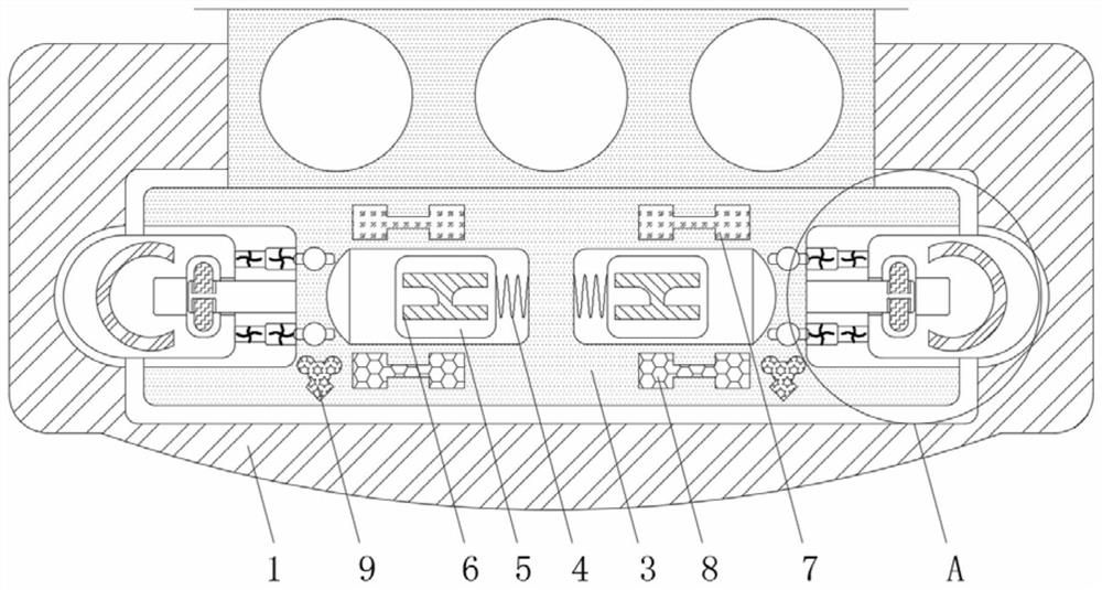
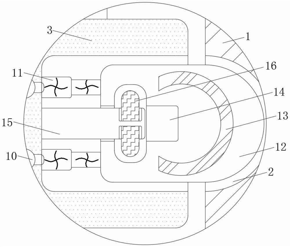
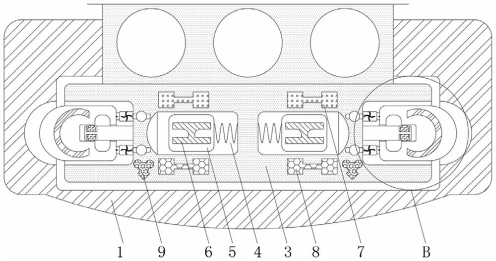
[0020] see Figure 1-4 , a new material stirring device that effectively prevents the stirring speed from being too fast, including a rotating shaft 1, the material of the rotating shaft 1 is a hard high-strength material and the shape of the rotating shaft 1 is cylindrical, and the rotating shaft 1 plays the role of fixing various components and transmission, The depth of the slot 2 is smaller than the width of the rotating shaft 1 and the shape of the slot 2...


PUM


Abstract

The invention provides a new material stirring device capable of effectively preventing too high stirring speed, and relates to the technical field of new materials. The devixce comprises a rotating shaft, the inner side of the rotating shaft is provided with uniformly distributed clamping grooves, the middle of the rotating shaft is rotatably connected with a rotating rod, the inner wall of the inner side of the rotating rod is fixedly connected with a spring, and the outer side of the spring is fixedly connected with a sliding block. The inner wall of the sliding block is fixedly connected with a dielectric plate, and the inner wall of the top of the rotating rod close to the top of the sliding block is fixedly connected with a positive plate. According to the new material stirring device capable of effectively preventing the too high stirring speed, through cooperative use of the electromagnet and the magnetic rod, when the rotating speed of the stirring device is too high, the electromagnet is powered on, the magnetic rod retracts into the guide rod under the action of magnetism, the conductive column is powered on, the electroactive rod retracts towards the inner side, thus clamping block can retract into the rotating rod, and the rotatng rod is enabled to idle in the rotating shaft, the situation that the stirring speed is too high is avoided, and the performance of the new material is effectively guaranteed.

Description

technical field [0001] The invention relates to the technical field of new materials, in particular to a new material stirring device which can effectively prevent the stirring speed from being too fast. Background technique [0002] New materials are a new type of material that we often use in our modern life. The current new materials are mainly for energy saving and environmental protection, so the production process will be more complicated than traditional materials. For example, some new materials are in the production In the process, it is often necessary to use a stirring device for sufficient stirring, but when the current stirring device is used, some problems often occur, which affect the performance of the new material. [0003] During the stirring process of the current new materials, not only need to stir fully, but also pay attention to the stirring speed. Once the stirring speed is greater than a certain value, the performance of the new material may be destr...

Claims


Application Information

Patent Timeline
IPC IPC(8): B01F15/00
CPCB01F35/30B01F35/3204
Inventor 刘惠豪
Owner 泗县米和花新材料科技有限公司
Why Eureka
Try Eureka