Cooking equipment
A technology for cooking equipment and pots, which is applied to cooking utensils, kitchen utensils, household utensils, etc., can solve problems such as affecting the service life of products and damage to electric heating plates under pressure.
- Summary
- Abstract
- Description
- Claims
- Application Information
AI Technical Summary
Problems solved by technology
Method used
Image
Examples
Embodiment 1
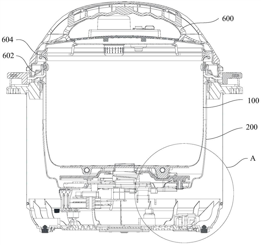
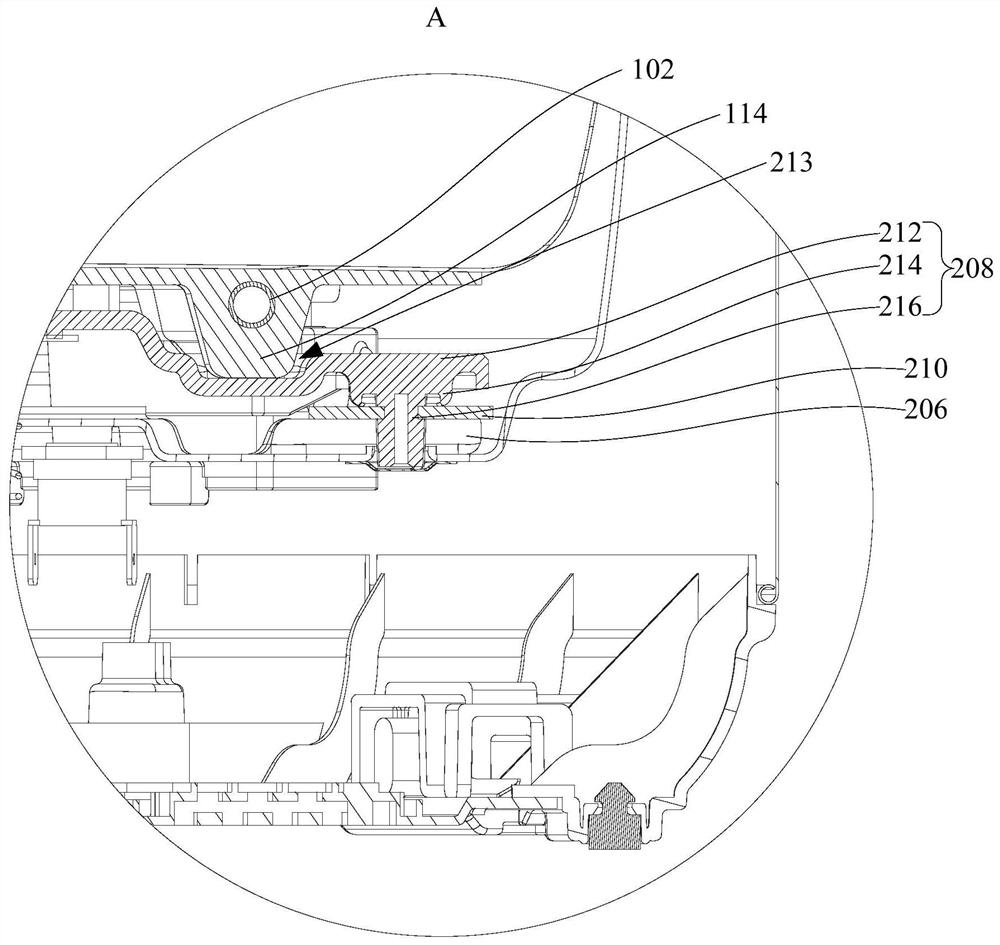
[0063] Such as figure 1 and figure 2 As shown, the first aspect of the present invention provides a cooking device, including: a pot body assembly 100 , a shell assembly 200 and a pressure bearing plate 208 .
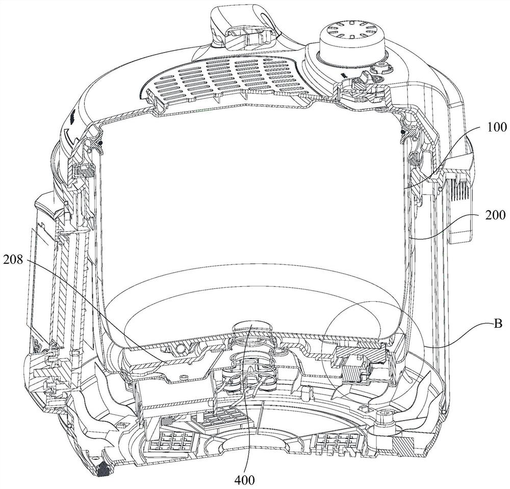
[0064] Specifically, the pot body assembly 100 is detachably arranged in the installation cavity of the housing assembly 200, the pot body assembly 100 includes a heating element 102, the bottom wall of the pot body assembly 100 is provided with a pressure-bearing boss 114, and in the installation cavity A pressure bearing plate 208 is provided for supporting the pot body assembly 100, by setting a pressure bearing boss 114 on the bottom wall of the pot body assembly 100, and setting a pressure bearing plate 208 between the pot body assembly 100 and the shell assembly 200 , the pressure-bearing boss 114 and the pressure-bearing plate 208 bear the pressure caused by the air pressure in the pot body assembly 100, so that when the pressure rises during the working proces...
Embodiment 2
[0069] Such as Figure 5 , Figure 6 and Figure 7 As shown, in any of the above embodiments, further, the pot body assembly 100 further includes: an inner pot 112, the heating element 102 is arranged on the bottom wall of the inner pot 112; The wall protrudes downward, and the downward protruding distance of the pressure-bearing boss 114 is greater than the downward protruding distance of the heating element 102 .
[0070] In this embodiment, the pot body assembly 100 also includes an inner pot 112, and the heating element 102 is arranged on the bottom wall of the inner pot 112. By setting the heating element 102 on the bottom wall of the inner pot 112, the heating element 102 generates The heat can directly heat the ingredients placed in the inner pot 112, further improving the heating efficiency of the product; the pressure-bearing boss 114 is arranged on the bottom wall of the inner pot 112 and protrudes downward, so that the pressure-bearing boss 114 is supported on Th...
Embodiment 3
[0077] Such as figure 1 , figure 2 and Figure 8 As shown, in any of the above embodiments, further, the housing assembly 200 includes: an outer pot 202 having an installation cavity;
[0078] The support part 206 protrudes from the bottom wall of the outer pot 202, one side of the elastic deformation member 210 abuts against the support part 206 and at least part of the elastic deformation member 210 is suspended. Specifically, the support portion 206 is protrudingly arranged on the bottom wall of the outer pot 202, the pressure bearing plate 208 is arranged on the bottom of the pot body assembly 100 for supporting the pot body assembly 100, and the elastic deformation member 210 is arranged on the pressure bearing plate 208 and the support. parts 206, and the elastic deformation member 210 abuts against the pressure bearing plate 208 and the support part 206 respectively. When the cooking equipment is in use, when the pressure inside the pot body assembly 100 rises, the ...
PUM
 Abstract
Description
Claims
Application Information
 - R&D Engineer
- R&D Manager
- IP Professional
- Industry Leading Data Capabilities
- Powerful AI technology
- Patent DNA Extraction
Browse by: Latest US Patents, China's latest patents, Technical Efficacy Thesaurus, Application Domain, Technology Topic, Popular Technical Reports.
© 2024 PatSnap. All rights reserved.Legal|Privacy policy|Modern Slavery Act Transparency Statement|Sitemap|About US| Contact US: help@patsnap.com


