A method for forming connection lines on a glass substrate through the exposure principle of an exposure machine

A technology of glass substrate and exposure machine, which is applied in the direction of circuit substrate materials, removal of conductive materials by chemical/electrolytic methods, printed circuits, etc., can solve the problems of low production efficiency, looseness, high production cost, etc., to improve production efficiency, The effect of reducing frame width and reducing production cost

Active Publication Date: 2022-04-29
广东科视光学技术股份有限公司
View PDF7 Cites 0 Cited by
  • Summary
  • Abstract
  • Description
  • Claims
  • Application Information

AI Technical Summary

Problems solved by technology

This method of using flexible circuit boards for transfer mainly has the following methods. First, the flexible circuit board has a certain thickness, and its winding and stretching also requires a certain space, which leads to a greater thickness of the entire glass substrate assembly, which is not conducive to display components. Second, the flexible circuit board is connected to the electronic circuits on both sides of the glass substrate by welding, and it will loosen after being subjected to a certain tension or used for a long time, which may cause the display components to work abnormally or even fail to work. Therefore, the reliability is poor; third, the operation process of welding the flexible circuit board is more complicated, the technical requirements are high, the production efficiency is low, and the production cost is also higher

Method used


Image

  • A method for forming connection lines on a glass substrate through the exposure principle of an exposure machine
  • A method for forming connection lines on a glass substrate through the exposure principle of an exposure machine

Examples


Embodiment Construction

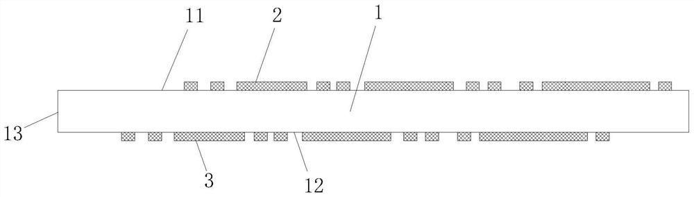
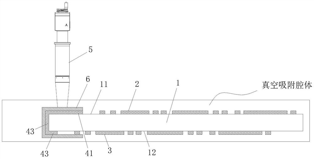
[0018] In this example, refer to figure 1 and figure 2 , the method of forming a connection line on a glass substrate through the exposure principle of an exposure machine, the glass substrate 1 includes an A surface 11, a B surface 12 and a side surface 13, and the thickness of the glass substrate 1 is 0.1-1mm; on the A surface 11 has A-side circuit 2, B-side 12 has B-side circuit 2, and a photolithography head 5 is respectively formed along A-side 11, B-side 12 and side 13 to form a connection circuit, and A-side circuit 2 is formed through the connection circuit. To achieve electrical interconnection with the line 3 on the B side, the implementation process is carried out according to the following steps,

[0019] S1. Clean the surface of the glass substrate 1, coat a layer of conductive material on the surface of the glass substrate 1, and then use a mask with a line and cooperate with UV ink to go through the exposure-development-etching process to make the A surface 11...


PUM

PropertyMeasurementUnit
thicknessaaaaaaaaaa

Abstract

The invention discloses a method for forming a connection circuit on a glass substrate through the exposure principle of an exposure machine. The glass substrate includes a surface A, a B surface and a side surface, and the A surface has an A surface circuit, and the B surface has a B surface circuit. The connecting lines are formed by exposing the A surface, the B surface and the side surface of the glass substrate through the photolithography head and the wrapping mask, and the connecting lines realize the electrical interconnection between the A surface circuit and the B surface circuit. In the present invention, a mask is prepared and coated on the exposed portion of the glass substrate, and then a photolithography head is used to align the edge mask for exposure to form an integral connection circuit, and the connection circuit connects the electronic circuits on the upper and lower sides of the glass substrate. Therefore, there is no need to use a flexible circuit board for switching, not only can reduce the thickness of the entire assembly of the glass substrate, but also the connection line formed by exposure has higher reliability, and there is no problem such as force pull-off; the connection line passes through the light The engraved head can be formed by exposure, and the operation is more convenient, which is conducive to improving production efficiency.

Description

technical field [0001] The invention relates to the technical field of manufacturing electronic display components, in particular to a method for connecting lines on both sides of a glass substrate. Background technique [0002] With the rapid development and wide application of various electronic devices, the requirements for display components are getting higher and higher, and the most important developments include thinning and reliability. In the display components, the glass substrate is a very important accessory. Generally, the front and back sides of the glass substrate are exposed to form electronic circuits. In order to connect the electronic circuits on both sides, a flexible circuit board (ie FPC) is usually used for switching. and outgoing. This method of using flexible circuit boards for transfer mainly has the following methods. First, the flexible circuit board has a certain thickness, and its winding and stretching also requires a certain space, which lead...

Claims


Application Information

Patent Timeline
Patent Type & Authority Patents(China)
IPC IPC(8): H05K3/06H05K1/02H05K1/03
CPCH05K3/064H05K1/0306H05K1/0296H05K2201/0108
Inventor 陈志特王华甘泉
Owner 广东科视光学技术股份有限公司
Why Eureka
Try Eureka