
Low-dropout voltage converter circuit and standby circuit system thereof

A voltage converter and low-dropout technology, applied in logic circuits, control/regulation systems, logic circuit interface devices, etc., can solve problems such as reducing battery standby time and increasing system standby power consumption, eliminating standby current and reducing standby power. The effect of reducing power consumption and standby power consumption

Pending Publication Date: 2021-07-16
GALAXYCORE SHANGHAI
View PDF0 Cites 0 Cited by
  • Summary
  • Abstract
  • Description
  • Claims
  • Application Information

AI Technical Summary

Problems solved by technology

However, the standby currents of bandgap references and voltage converters usually range from tens of microamps to hundreds of microamps. These standby currents increase the system's standby power consumption and reduce the battery standby time of mobile devices.

Method used


Image

  • Low-dropout voltage converter circuit and standby circuit system thereof
  • Low-dropout voltage converter circuit and standby circuit system thereof
  • Low-dropout voltage converter circuit and standby circuit system thereof

Examples


Embodiment Construction

[0022] In the following description, numerous specific details are set forth in order to provide a thorough understanding of the present invention. However, the present invention can be implemented in many other ways different from those described here, and those skilled in the art can make similar extensions without violating the connotation of the present invention, so the present invention is not limited by the specific implementations disclosed below.

[0023] Secondly, the present invention is described in detail by means of schematic diagrams. When describing the embodiments of the present invention in detail, for convenience of explanation, the schematic diagrams are only examples, which should not limit the protection scope of the present invention.

[0024] In order to make the above objects, features and advantages of the present invention more comprehensible, a low-dropout voltage converter circuit of the present invention will be described in detail below with refer...


PUM


Abstract

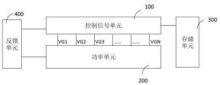
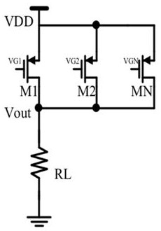
The invention provides a low-voltage-drop voltage converter circuit and a standby circuit system thereof, and the low-voltage-drop voltage converter circuit comprises a power unit, a control signal unit and a storage unit. The storage unit is suitable for storing control signals VG1-VGN in the control signal unit when the output voltage of the power unit is in a voltage range and load resistance required by a standby system; and the control signal unit is suitable for calling the value of each control signal VG1-VGN in the storage unit when the standby system enters a standby state so as to control the conduction degree or the on-off state of a corresponding power device in the power unit. The low-voltage-drop voltage converter circuit and the standby circuit system thereof can reduce standby power consumption.

Description

technical field [0001] The invention relates to the technical field of electronic circuits, in particular to a low-drop voltage converter circuit and a standby circuit system thereof. Background technique [0002] The existing standby scheme is that when the system enters the standby state, the bandgap reference cooperates with a voltage regulator (voltage regulator) to supply power to the system. However, the standby currents of bandgap references and voltage converters usually range from tens of microamps to hundreds of microamps. These standby currents increase system standby power consumption and reduce battery standby time of mobile devices. Contents of the invention [0003] The purpose of the present invention is to provide a low-drop voltage converter circuit and its standby circuit system, so as to solve the technical problem of standby current in the system standby in the prior art. [0004] In order to solve the above technical problems, the present invention p...

Claims


Application Information

Patent Timeline
IPC IPC(8): H03K19/00H03K19/0175G05F1/575
CPCG05F1/575H03K19/0008H03K19/0013H03K19/0016H03K19/017509H03K19/017581
Inventor 李怀兆王茂林
Owner GALAXYCORE SHANGHAI
Learn More