
Standby Power Consumption Limiting Device

a technology of power consumption limitation and standby current, which is applied in the direction of coupling device connection, television system, instruments, etc., can solve the problems of inconvenient restoration of power in the prior art or the inability to describe a convenient mechanism for restoring power, and achieve the effect of eliminating the current of standby and facilitating the restoration of power

Inactive Publication Date: 2010-08-05
ECO TECH CORP
View PDF3 Cites 35 Cited by
  • Summary
  • Abstract
  • Description
  • Claims
  • Application Information

AI Technical Summary

Benefits of technology

[0014]The invention enables power restoration, simply in response to operation of the appliance on / off switch and does not require a more costly remote control arrangement communicating with the device. Nor does it require backup batteries. This is not only a cheaper solution but also overcomes the problem that the device, if it is a plug or socket, is unlikely to be easily manually accessible or have line of sight visibility to a remote control signal. Thus this invention not only eliminates the standby current of such appliances, by turning the appliance off after it has been placed in standby mode, but also enables the easy restoration of power when someone wants to use the appliance again. It will be realised that, when the power switching means is switched back to its first state, thereby restoring the power connection, the appliance switch will then be in the “off” position and will therefore need switching to the “on” position to render the appliance operational again.

Problems solved by technology

The prior art therefore either does not describe a convenient mechanism for restoring power after a standby supply has been automatically turned off.

Method used


Image

  • Standby Power Consumption Limiting Device
  • Standby Power Consumption Limiting Device
  • Standby Power Consumption Limiting Device

Examples


Embodiment Construction

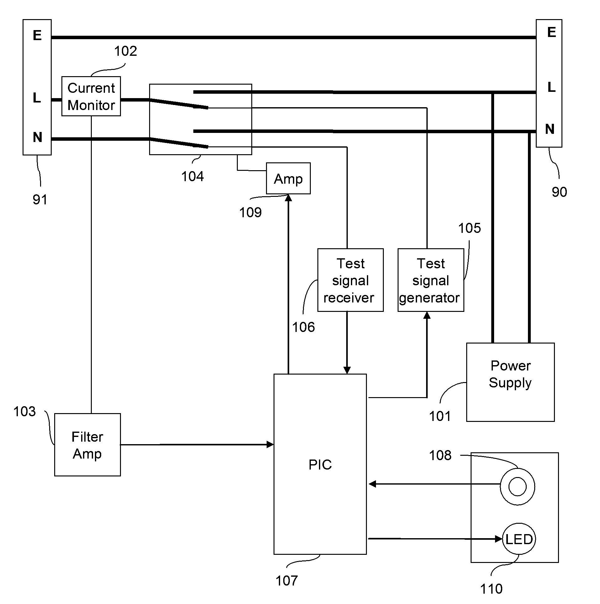
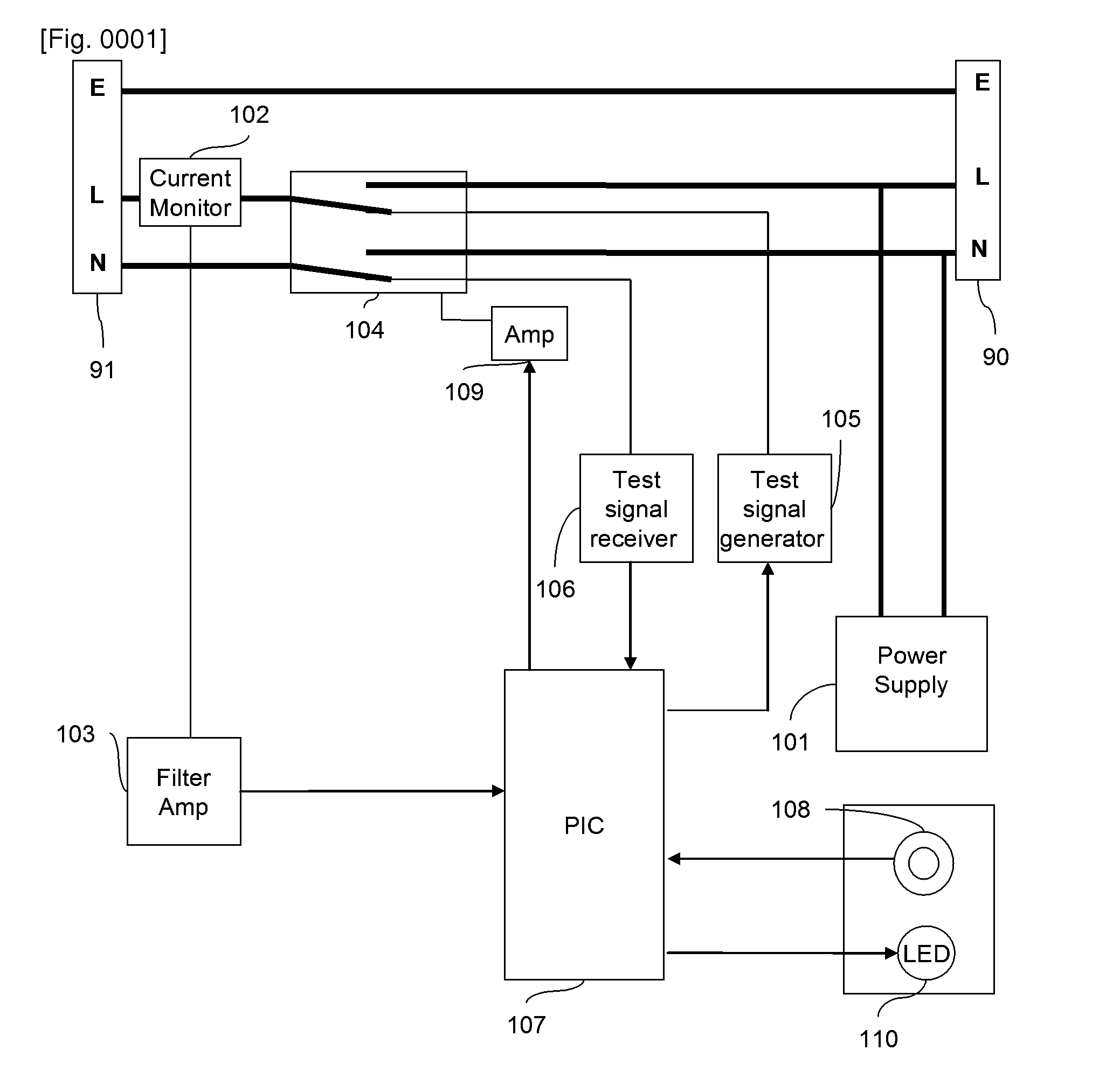
[0029]FIG. 1 shows a standby power consumption limiting device in the form of an adapter interposed between an electricity supply outlet 90 and the input terminals 91 or plug connection of an electrical appliance (not shown) which is capable of going into a standby power mode of operation. The power supply is assumed to be a single phase supply, having Live (L), Neutral (N) and Earth (E) connections. An AC voltage is supplied between the Live and Neutral terminals. In normal operation of the appliance, power from outlet 90 is connected to appliance input terminals 91 via a double-pole double-throw relay 104 with its contacts held in a closed position, corresponding to a first state. The relay is held closed as long as a control signal from an amplifier 109 is provided.

[0030]Power for the standby power consumption limiting device is supplied by an auxiliary power supply 101 which takes mains AC and transforms and regulates it down to the (generally) 5v DC needed to power other compon...


PUM


Abstract

A standby power consumption limiting device is provided for connection between an electricity supply and an electrical appliance of the kind having a main on / off switch, two power supply input terminals and a standby mode control circuit operable, when the appliance is switched “on”, to place the appliance in a reduced power standby mode. The device comprises standby mode detection means (102,103) effective to detect and indicate that the appliance has gone into standby mode and power switching means (104) having a first state in which the electricity supply is connected to the appliance via its power supply input terminals and a second state in which the electricity supply is disconnected from the appliance. A power switch control means (107) responds to an indication from the standby mode, by switching the power switching means from its first state to its second state, thereby removing power from the appliance. At this point, a test signal generating means (105), connected to one of the appliance input terminals by the power switching means when in its second state, generates a test signal of predetermined form, said test signal being returned, while the appliance main switch is in the “on” state, via the other appliance input terminal. A test signal detection means (106), connected to said other appliance input terminal by the power switching means when in its second state, is capable of detecting the test signal returned via said other terminal, when the appliance main switch is in its “on” state and of detecting a predetermined change in the returned test signal indicative of the appliance main switch having been turned to its “off” state. The power switch control means is responsive to an indication from the test signal detection means that the appliance main switch has turned been turned “off” to put the power switching means back into its first state thereby restoring power to the appliance which will then become active when its power switch is returned to the on position.

Description

FIELD OF THE INVENTION[0001]The present invention relates to devices for limiting power consumption and, in particular, to devices for turning off the power supply to an electrical appliance operating in standby mode.BACKGROUND OF THE INVENTION[0002]Many electrical appliances, for example televisions and other household appliances, have both an active, fully powered, mode of operation and one or several power saving modes, known as standby modes. In a standby mode, the appliance consumes significantly less power than when it is fully active. In the case of a television, the standby mode is typically initiated by operation of a remote control by the user as an alternative to switching the device off at the supply. Full operation can be resumed quickly by operation of the remote control.[0003]In the case of a television, both picture display and sound system will be off in standby mode but the infra-red detector for sensing signals from the remote control will remain powered, as may o...

Claims


Application Information

Patent Timeline
Patent Type & Authority Applications(United States)
IPC IPC(8): G05F1/10
CPCH04N5/63H02J9/005H01R13/70H02H3/12
Inventor STANFORD-CLARK, ANDREW JAMES
Owner ECO TECH CORP
Learn More