Dimension measuring device integrating 2D camera and 3D laser
A measuring device and 3D technology, applied in the direction of measuring devices, optical devices, instruments, etc., can solve the problems of large equipment volume, large measurement error, easy data deviation, etc., to achieve a high degree of automation, reduce equipment volume, and positioning accuracy. high effect
- Summary
- Abstract
- Description
- Claims
- Application Information
AI Technical Summary
Problems solved by technology
Method used
Image
Examples
Embodiment 1
[0080] This embodiment introduces a dimension measuring device integrating a 2D camera and a 3D laser by taking a wristwatch as an example.
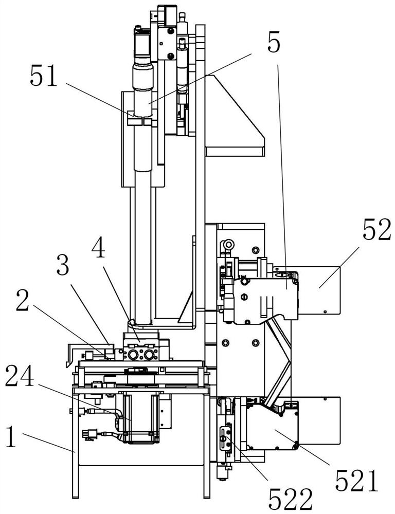
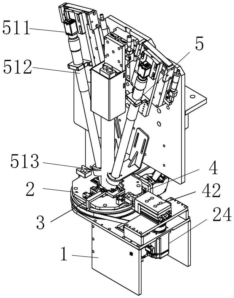
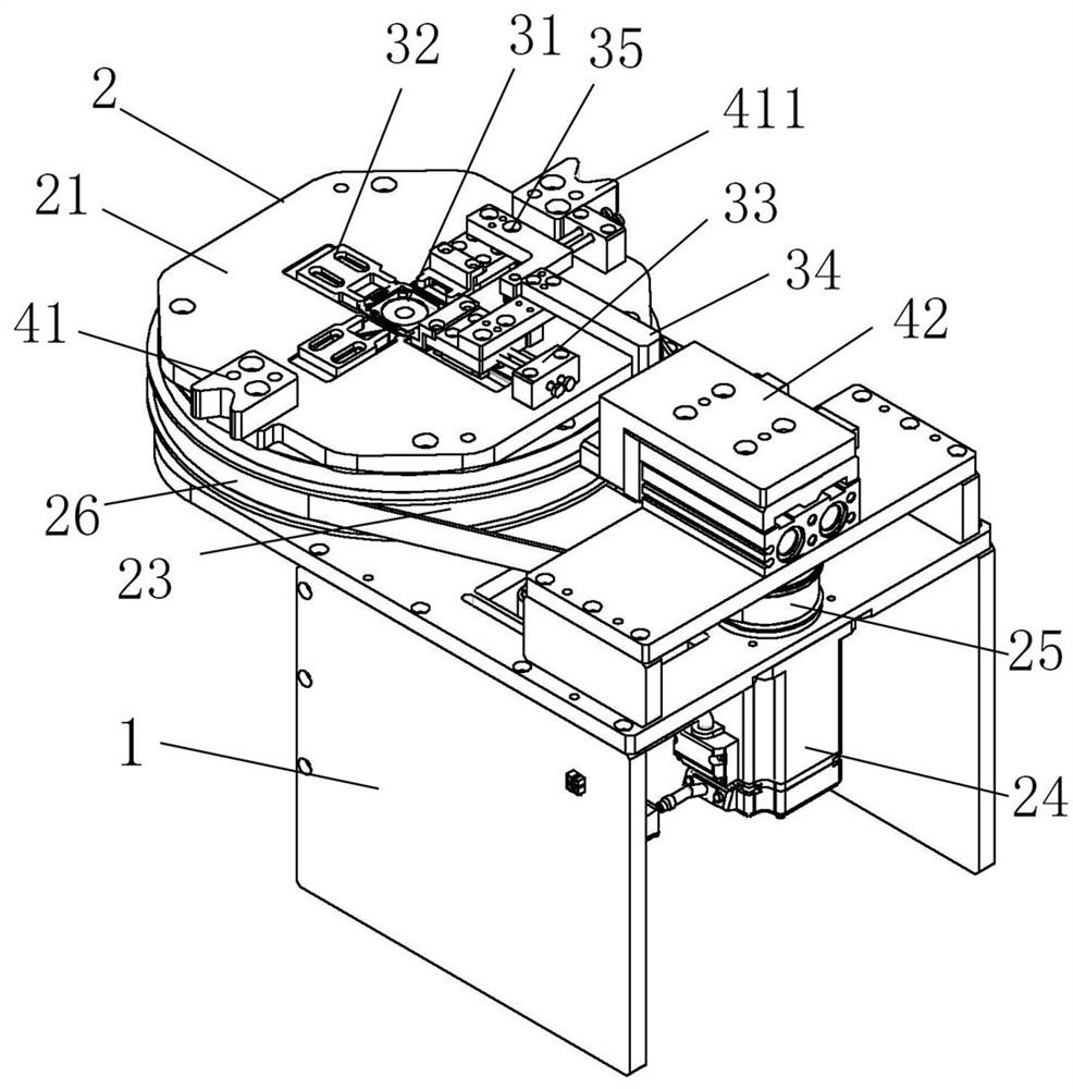
[0081] as attached figure 1 , attached image 3 And attached Figure 6 As shown, a size measuring device integrating a 2D camera and a 3D laser includes a bracket 1 on which a rotating device 2, a product fixing component 3, a positioning device 4, a measuring device 5 and a control system are integrated;
[0082] The rotating device 2 is arranged above the support 1, and the rotating device 2 includes a turntable 21, a collar 22 arranged below the turntable 21, a first synchronous pulley 23 arranged on the periphery of the collar 22, and used to drive the rotating The drive motor 24 that device 2 rotates;
[0083] The product fixing assembly 3 is arranged on the rotating device 2, and the product fixing assembly 3 includes a product carrier 31, a product limiting block 32 for fixing the product carrier 31 and a product carrier for fi...
Embodiment 2
[0127] This embodiment is carried out on the basis of the first embodiment above, and the similarities with the first embodiment will not be repeated.
[0128] The product limiting block and the fixing device are distributed around the product carrier, the fixing device includes a first fixing device, and the first fixing device includes a first sliding device connected to the first sliding device. A pressing plate on the device and a first product fixing block connected to the first sliding device for fixing products; a stretching device is connected to the pressing plate.
[0129] Further, the spreading device includes a spreading block and a spreading cylinder, a spreading bracket is arranged between the spreading cylinder and the spreading block, and a space between the spreading block and the spreading bracket can be To disassemble the connection, the expansion cylinder is used to control the connection or disassembly between the expansion block and the expansion bracket....
Embodiment 3
[0133] This embodiment is carried out on the basis of the first embodiment above, and the similarities with the first embodiment will not be repeated.
[0134] The product limiting block and the fixing device are distributed around the product carrier, and the fixing device includes a second fixing device.
[0135] Further, the second fixing device includes a second sliding device, a second sliding block arranged on the second sliding device, and a second product fixing block connected with the second sliding block, the second sliding block is below the second sliding block An unlocking device is provided, and the unlocking device includes an unlocking connection wedge and an unlocking cylinder, and the unlocking connection wedge is arranged on the turntable and elastically connected with the turntable.
[0136] Further, the elastic connection between the unlocking connection wedge and the turntable is realized by a spring.
[0137] Further, the second sliding block drives th...
PUM
| Property | Measurement | Unit |
|---|---|---|
| Diameter | aaaaa | aaaaa |
| Thickness | aaaaa | aaaaa |
Abstract
Description
Claims
Application Information
 - Generate Ideas
- Intellectual Property
- Life Sciences
- Materials
- Tech Scout
- Unparalleled Data Quality
- Higher Quality Content
- 60% Fewer Hallucinations
Browse by: Latest US Patents, China's latest patents, Technical Efficacy Thesaurus, Application Domain, Technology Topic, Popular Technical Reports.
© 2025 PatSnap. All rights reserved.Legal|Privacy policy|Modern Slavery Act Transparency Statement|Sitemap|About US| Contact US: help@patsnap.com


