
Visual detection assembly table

A visual inspection and assembly platform technology, applied in metal processing, metal processing equipment, manufacturing tools, etc., can solve the problems of low work efficiency, dislocation of mounting holes, difficult to turn over and transfer screw installation, etc., and achieve the effect of high work efficiency

Pending Publication Date: 2021-07-16
YALONG INTELLIGENT EQUIP GRP CO LTD
View PDF0 Cites 1 Cited by
  • Summary
  • Abstract
  • Description
  • Claims
  • Application Information

AI Technical Summary

Problems solved by technology

UHF RFID technology is a non-contact automatic identification technology, which automatically identifies target objects and obtains relevant data through radio frequency signals without establishing mechanical or optical contact between the identification system and specific targets. The advantages of long distance, long service life, good environmental adaptability, and simultaneous identification of multiple tags have been applied to varying degrees in recent years. Since electronic tags are usually composed of chips and shells connected by screws, and most common electronic tags are centered , during the assembly process, the chip or the shell is extremely prone to deflection, which makes the mounting holes dislocated and cannot be installed directly. It is necessary to use manual or robotic hands to adjust the angle or position of the chip or shell and then install it again. Not only is the work efficiency low, but the installation is complete. It is not easy to turn over and transfer to carry out screw installation in the next process

Method used


Image

  • Visual detection assembly table
  • Visual detection assembly table
  • Visual detection assembly table

Examples


Embodiment Construction

[0023] The following will clearly and completely describe the technical solutions in the embodiments of the present invention with reference to the accompanying drawings in the embodiments of the present invention. Obviously, the described embodiments are only some, not all, embodiments of the present invention. Based on the embodiments of the present invention, all other embodiments obtained by persons of ordinary skill in the art without making creative efforts belong to the protection scope of the present invention.

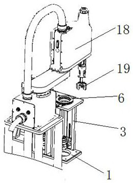
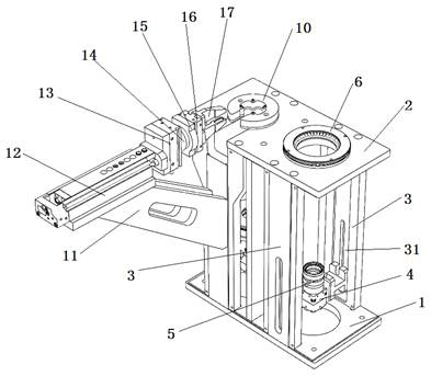
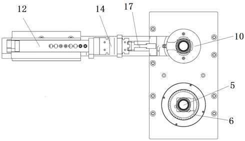
[0024] refer to Figure 1 to Figure 6 To further explain this application, such as figure 1 , figure 2 , image 3 and Figure 4 A kind of visual detection assembly platform shown, comprises assembly platform and is arranged on the robot 18 of described assembly platform side, is provided with gripper 19 on the mechanical arm of described robot 18, and described assembly platform comprises assembly platform body, so The assembly table body includes a lower...


PUM


Abstract

The invention discloses a visual detection assembly table. The visual detection assembly table comprises an assembly platform and a robot arranged on one side of the assembly platform, a mechanical arm of the robot is provided with a clamping jaw, the assembly platform comprises an assembly table body, an upper panel of the assembly table body is provided with two detection avoiding through holes, and the assembly table body is provided with two sets of visual detection mechanisms with adjustable height positions; the two sets of visual detection mechanisms correspond to the two detection avoiding through holes in a one-to-one mode, a center hole of a positioning mechanism arranged on the upper panel and one detection avoiding through hole are coaxially formed, and a turnover mechanism arranged on one side of the assembly table body is used for clamping and turning over an assembly component placed on the positioning mechanism; and a plurality of bosses are arranged on the top face of the positioning mechanism, positioning pins capable of floating up and down are arranged on the bosses, and the positioning pins are used for product positioning or dislocation buffering. According to the visual detection assembly table, accurate mounting can be met, the working efficiency is high, and an assembly part can be conveniently turned over for screw mounting.

Description

technical field [0001] The invention relates to the technical field of electronic label production, in particular to a visual detection assembly platform. Background technique [0002] The Internet of things (Internet of things) is an important trend in the development of information networks at present. It is called the third wave of the world's information industry after computers and the Internet. Radio frequency identification technology UHF RFID is one of the key technologies of the Internet of things. UHF RFID technology is a non-contact automatic identification technology, which automatically identifies target objects and obtains relevant data through radio frequency signals, without the need to establish mechanical or optical contact between the identification system and specific targets. The advantages of long distance, long service life, good environmental adaptability, and simultaneous identification of multiple tags have been applied to varying degrees in recent ...

Claims


Application Information

Patent Timeline
Patent Type & Authority Applications(China)
IPC IPC(8): B23P19/00B23P19/06B23P19/10
CPCB23P19/00B23P19/001B23P19/06B23P19/10
Inventor 陈继权叶明闯陈钰生吴小兵许莉红郑璋章灵敏朱信忠
Owner YALONG INTELLIGENT EQUIP GRP CO LTD
Learn More