
Production and manufacturing method of copper bar body

A manufacturing method and rod body technology, which is applied in the field of insulating rigid cable components, socket connectors, and copper bar rods, can solve the problem of high structural strength of copper bar cable components, difficulty in controlling internal space, and difficulty in achieving structural strength and insulation performance Higher requirements and other issues, to achieve the effect of improving insulation performance and copper bar bonding strength and environmental reliability, reducing processing defect rate and process difficulty, improving structural characteristics and processing feasibility

Active Publication Date: 2021-07-13
CHINA AVIATION OPTICAL-ELECTRICAL TECH CO LTD
View PDF8 Cites 2 Cited by
  • Summary
  • Abstract
  • Description
  • Claims
  • Application Information

AI Technical Summary

Problems solved by technology

[0002] At present, in the field of connectors, printed boards are generally connected to the internal contacts of the connector through cable crimping or welding, which is low in assembly efficiency and difficult to maintain and disassemble.
The structural strength of the copper row cable assembly is relatively high. At present, similar products on the market use FR4 milling to form I-shaped grooves on both sides, insert copper strips into the grooves and then seal the surface. It is difficult to meet higher requirements for structural strength and insulation performance.
In addition, the manufacturing cost is high, the milling groove is complicated in the process, and it is difficult to control the internal space. The filling often needs to be filled with glue, the production efficiency is low, and the copper bar contacts produced cannot be quickly plugged and switched. characteristics

Method used


Image

  • Production and manufacturing method of copper bar body
  • Production and manufacturing method of copper bar body
  • Production and manufacturing method of copper bar body

Examples


Embodiment Construction

[0035] Further detailed description will be made below in conjunction with the accompanying drawings and preferred embodiments.

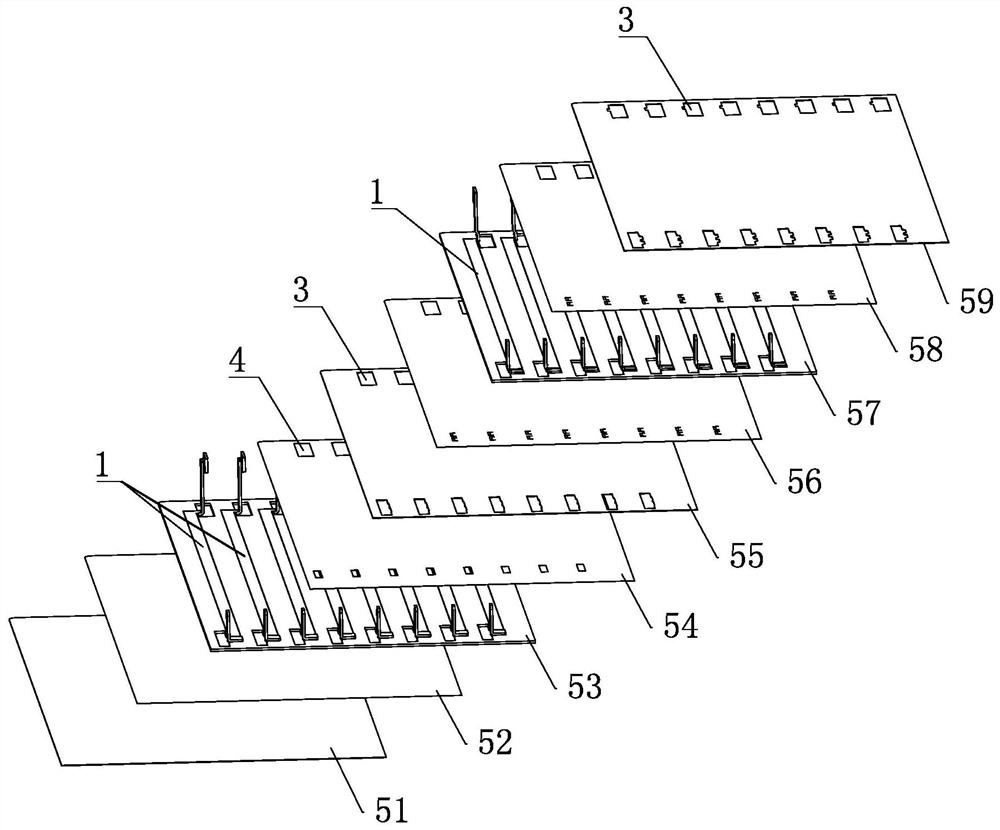
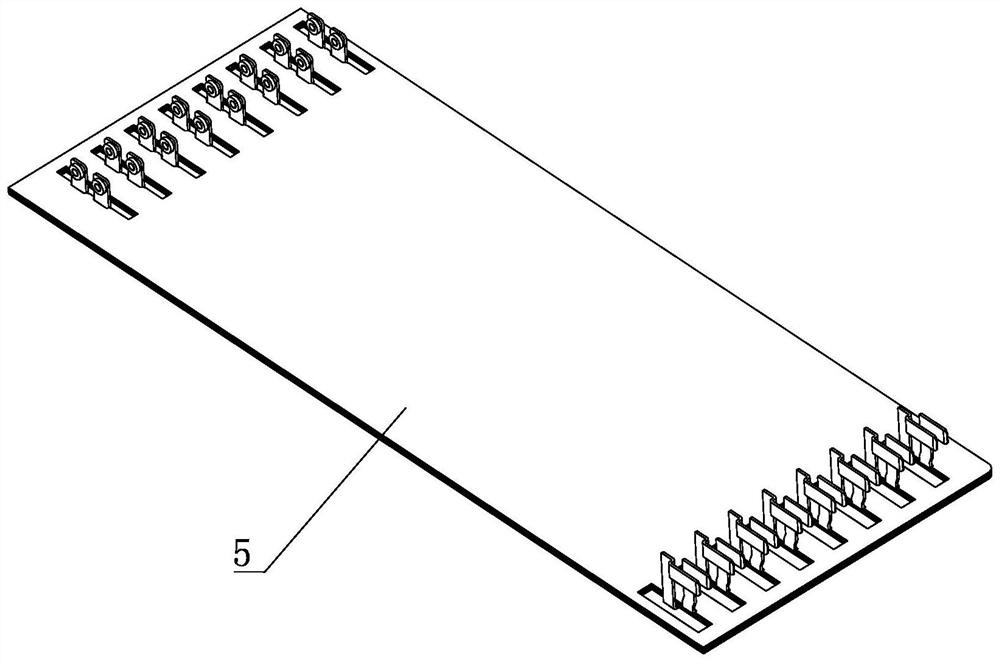
[0036] An embodiment of a manufacturing method for a copper row bar body, combining Figure 1 to Figure 7 , including the following steps:

[0037] According to the specifications of the final forming of the copper bar body, a plurality of copper bars 1 are stamped in batches, and the front and rear ends of each copper bar are respectively bent so that the front end of the copper bar has a front contact 11, and the rear end of the copper bar has a rear contact. The end contact piece 12, the front / rear end contact piece is perpendicular to the plane where the copper bar is located, and then the copper bar is deburred to make the surface of the copper bar smooth; then the deburred copper bar is subjected to overall electroplating treatment to improve the oxidation resistance .

[0038] Prepare a plurality of insulating boards. In this embodiment, th...


PUM


Abstract

A production and manufacturing method of a copper bar body comprises the following steps: manufacturing a copper bar through stamping, bending the two ends of the copper bar to form a front-end contact piece and a rear-end contact piece, and deburring the copper bar; according to the shape and size of the copper bars, processing a plurality of through hole grooves which are through up and down in an insulating plate, embedding the copper bars in the corresponding through hole grooves, and processing windows for exposing the front-end contact piece and the rear-end contact piece at the two ends of the insulating plate; cutting the prepreg, and forming through holes for avoiding the front-end contact piece and the rear-end contact piece in the prepreg; then carrying out typesetting in a stacking form; putting the multi-layer stacked body, obtained after typesetting is completed, into a pressing machine to be subjected to hot pressing; and finally, processing the multi-layer stacked body after hot pressing into a plurality of copper bar bodies. The manufacturing process is simple, the production efficiency is high, and the produced copper bar body product is good in structural strength and insulating property, has the characteristic of quick plugging and switching of electric energy or signals, and is convenient to disassemble and maintain when being applied to the field of connectors.

Description

technical field [0001] The invention belongs to the technical field of connectors, and in particular relates to a copper row bar body, an insulating hard cable assembly and a socket connector. Background technique [0002] At present, in the field of connectors, printed boards are generally connected to the internal contacts of the connector through cable crimping or welding, which makes the assembly efficiency low and difficult to maintain and disassemble. The structural strength of the copper row cable assembly is relatively high. At present, similar products on the market use FR4 milling to form I-shaped grooves on both sides, insert copper strips into the grooves and then seal the surface. It is difficult to meet higher requirements for structural strength and insulation performance. . In addition, the manufacturing cost is high, the milling groove is complicated in the process, and it is difficult to control the internal space. The filling often needs to be filled with...

Claims


Application Information

Patent Timeline
Patent Type & Authority Applications(China)
IPC IPC(8): H01R43/16H01R43/20
CPCH01R43/16H01R43/20
Inventor 李桥飞李敬冯冲
Owner CHINA AVIATION OPTICAL-ELECTRICAL TECH CO LTD
Learn More