Auxiliary equipment for self-power-off protection of drilling electromechanical equipment according to building resistance

A technology of electromechanical equipment and auxiliary equipment, applied in the direction of protection switch operation/release mechanism, circuit, electric switch, etc., can solve problems such as personal injury, drill breakage, drilling equipment damage, etc.

Inactive Publication Date: 2021-07-13
厦门胜浩贸易有限公司
View PDF0 Cites 0 Cited by
  • Summary
  • Abstract
  • Description
  • Claims
  • Application Information

AI Technical Summary

Problems solved by technology

[0003] The current drilling equipment needs the operator to apply a pressure to the building synchronously during the use process, and because the force is mutual, the drilling equipment at this time will also be subjected to a reaction force, and during the drilling process If you encounter extremely solid objects such as steel bars, excessive pressure will easily cause damage to the drilling equipment, ranging from the burning of the drilling motor to the serious injury of the drill bit, and often in the process of drilling. A large amount of dust, which often needs to be cleaned from the hole after the drilling is completed, and the dust scattered in the air during the cleaning process is also a kind of pollution to the environment

Method used


Image

  • Auxiliary equipment for self-power-off protection of drilling electromechanical equipment according to building resistance
  • Auxiliary equipment for self-power-off protection of drilling electromechanical equipment according to building resistance
  • Auxiliary equipment for self-power-off protection of drilling electromechanical equipment according to building resistance

Examples


Embodiment Construction

[0024] The following will clearly and completely describe the technical solutions in the embodiments of the present invention with reference to the accompanying drawings in the embodiments of the present invention. Obviously, the described embodiments are only some, not all, embodiments of the present invention. Based on the embodiments of the present invention, all other embodiments obtained by persons of ordinary skill in the art without making creative efforts belong to the protection scope of the present invention.

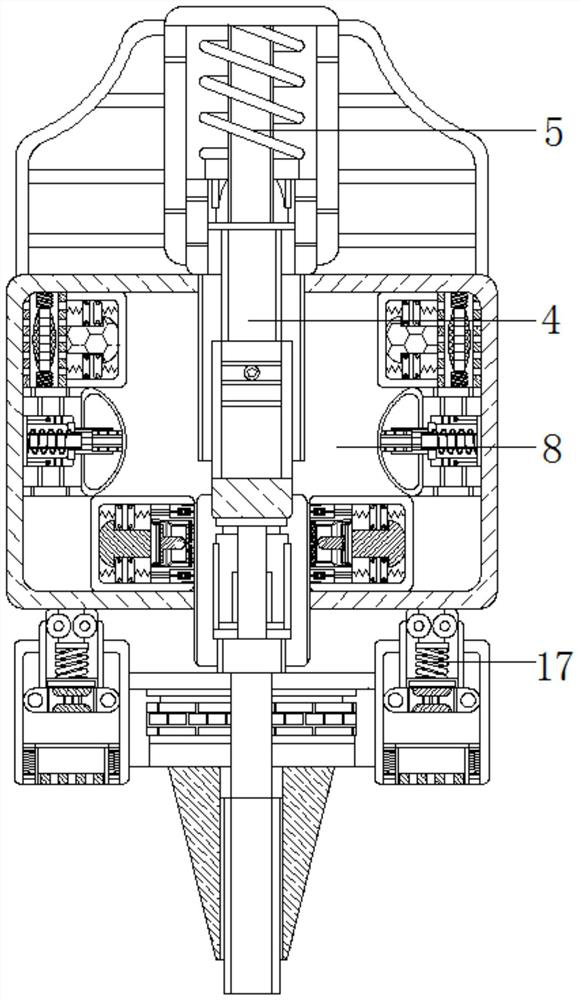
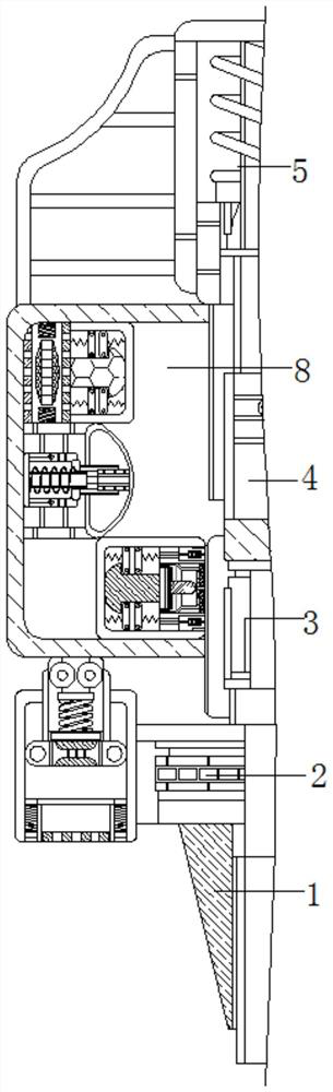
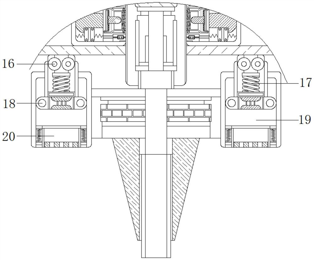
[0025] see Figure 1-5 , an auxiliary device for self-power-off protection according to building resistance for drilling electromechanical equipment, including a mounting base 1, a protective plate 2 fixedly connected to the top of the mounting base 1, a guide rod 3 fixedly connected to the top of the protective plate 2, and a guide rod 3. The top is fixedly connected with a support rod 4, and the top of the support rod 4 is movably connected with a return spr...


PUM


Abstract

The invention relates to the technical field of electromechanical equipment, and discloses auxiliary equipment for self-power-off protection of drilling electromechanical equipment according to building resistance, the auxiliary equipment comprises a mounting seat, a protection plate is fixedly connected to the top of the mounting seat, a guide rod is fixedly connected to the top of the protection plate, and a supporting rod is fixedly connected to the top of the guide rod; the top of the supporting rod is movably connected with a reset spring, the left side and the right side of the guide rod are both movably connected with electric blocks, and the resistance borne by the mounting base is increased, so that the reset spring is compressed to drive the shunting contact to slide in the limiting cavity along the guide block till the shunting contact makes contact with the electrified contact. When the shunting contact is in contact with the electrifying contact, the circuit is switched on, at the moment, current flows into the electrifying circuit through the electric block and then flows into the shunting resistor through the electrifying circuit, so that the shunting resistor is electrified, and the effects that the rotating speed of the drill bit is automatically reduced and the drill bit is contracted to prevent the drill bit from being broken when the resistance of a hard object is too large in the drilling process are achieved.

Description

technical field [0001] The invention relates to the technical field of electromechanical equipment, in particular to an auxiliary equipment for self-power-off protection according to building resistance for drilling electromechanical equipment. Background technique [0002] Electromechanical equipment generally refers to electrical appliances, machinery, electrical automation equipment, etc. Drilling equipment is a kind of electromechanical equipment. Nowadays, drilling equipment is used in the construction of buildings and the installation of large electromechanical equipment. It has been integrated into the It has become one of the irreplaceable electromechanical devices in people's lives. [0003] The current drilling equipment needs the operator to apply a pressure to the building synchronously during the use process, and because the force is mutual, the drilling equipment at this time will also be subjected to a reaction force, and during the drilling process If you en...

Claims


Application Information

Patent Timeline
IPC IPC(8): H01H71/10H01H15/14
CPCH01H15/14H01H71/10
Inventor 潘紫婷
Owner 厦门胜浩贸易有限公司
Why Eureka
Try Eureka