Eureka AIR delivers breakthrough ideas for toughest innovation challenges, trusted by R&D personnel around the world.

Turbulent flow threaded hole cooling structure for trailing edge of turbine blade and turbine blade

A technology for turbine blades and cooling structures, applied in the direction of blade support elements, machines/engines, mechanical equipment, etc., can solve the problems of insufficient cooling, ignoring the cooling of the surface of the partition rib, and low cooling efficiency of the surface of the partition rib, etc., to achieve good processing Integral, improved overall cooling effect, good heat transfer and cooling characteristics

Active Publication Date: 2021-07-13
NORTHWESTERN POLYTECHNICAL UNIV
View PDF6 Cites 1 Cited by
  • Summary
  • Abstract
  • Description
  • Claims
  • Application Information

AI Technical Summary

Problems solved by technology

[0005] Aiming at the problem that the cooling of the surface of the partition rib is neglected in the design stage of the cooling structure of the trailing edge in the prior art, and the cooling efficiency of the surface of the partition rib is low due to the insufficient cooling of the side near the suction side of the trailing edge, the present invention proposes a method for Spoiler screw hole cooling structure on the trailing edge of the turbine blade

Method used


Image

  • Turbulent flow threaded hole cooling structure for trailing edge of turbine blade and turbine blade
  • Turbulent flow threaded hole cooling structure for trailing edge of turbine blade and turbine blade
  • Turbulent flow threaded hole cooling structure for trailing edge of turbine blade and turbine blade

Examples


Embodiment Construction

[0025] This embodiment is a specific implementation case of the cooling structure with spoiler threaded holes on the trailing edge of the turbine blade.

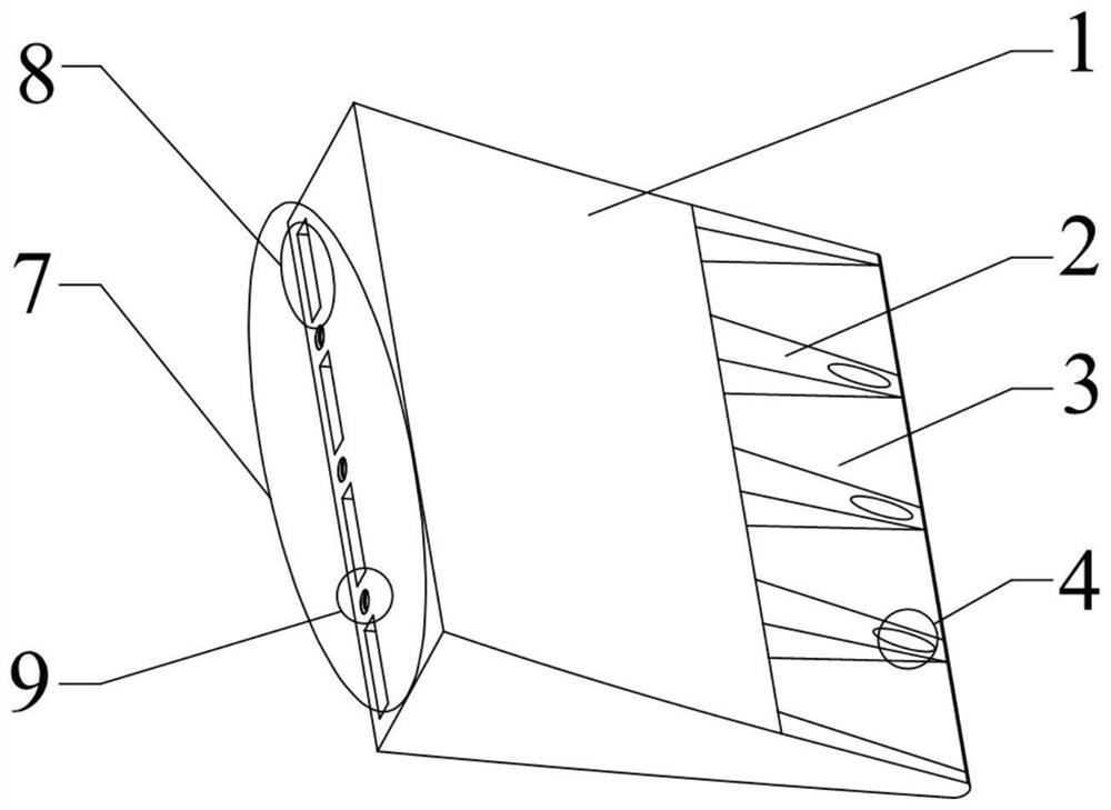
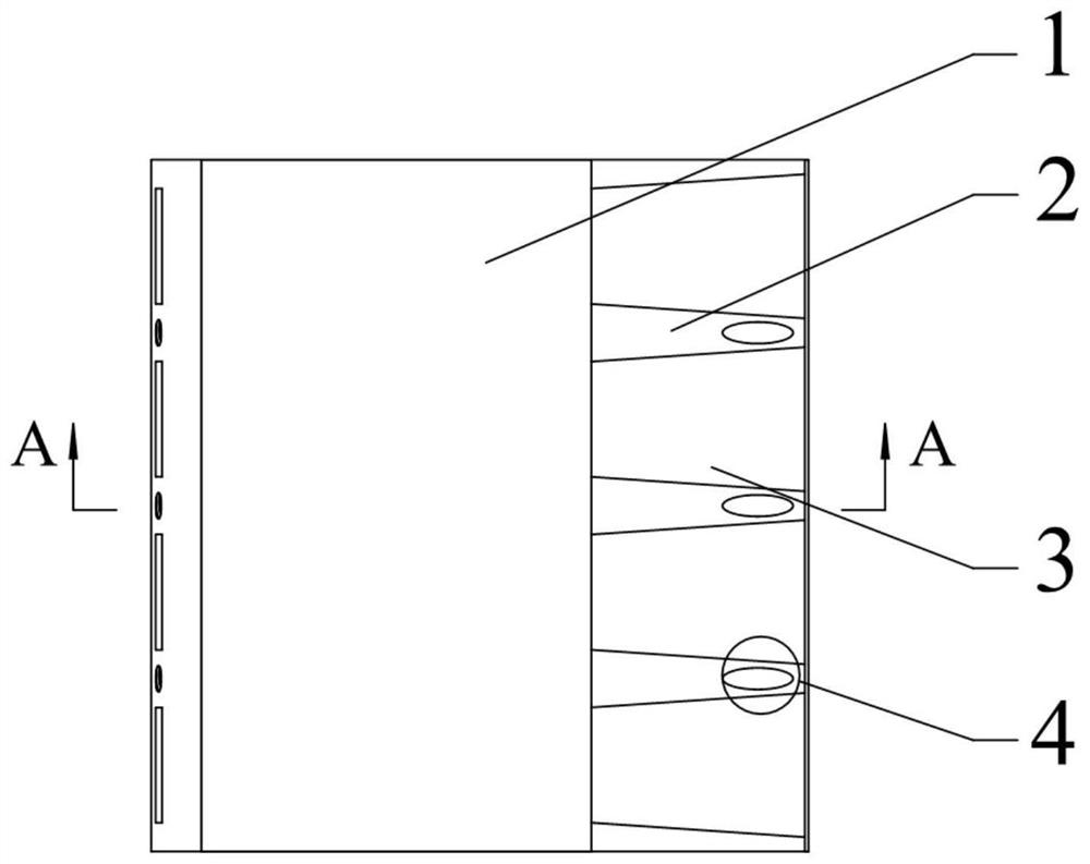
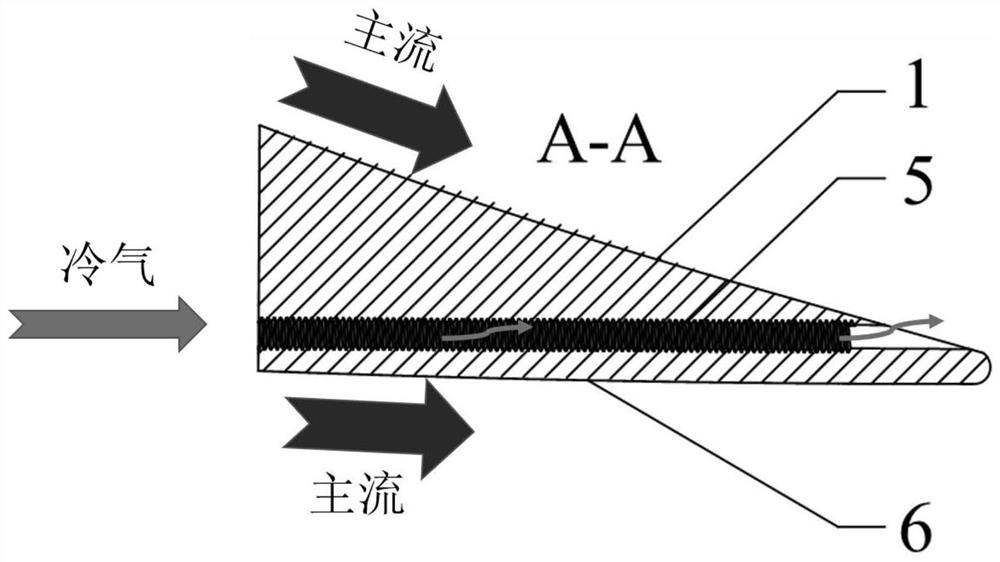
[0026] refer to figure 1 , figure 2 , image 3 , Figure 4 , Figure 5 , this kind of spoiler screw hole cooling structure for the trailing edge of the turbine blade and its application and arrangement position on the turbine blade are introduced in detail.

[0027] This embodiment is a trailing edge cooling structure with spoiler threaded holes on a certain type of turbine working blade. The cooling air flows through the cold flow inlet 7 into the trailing edge cooling structure with spoiler threaded holes. Slit cold air intake cavity 8 and partition rib cooling hole inlet 9 are two inlets of cooling air flow, and the cooling air flow entering the trailing edge cold air intake cavity 8 is sprayed out and covered on the trailing edge half-slit surface 3 to form a cooling air film, thereby cooling The pressure surface 1...


PUM


Abstract

The invention provides a turbulent flow threaded hole cooling structure for a trailing edge of a turbine blade, which is arranged in the trailing edge area of the turbine blade, and is formed by cutting off part of the wall surface of a pressure surface of the trailing edge of the turbine blade, only reserving the wall surface on one side of a suction surface and arranging a plurality of separation ribs. Cylindrical cooling holes which penetrate through the separation ribs along the flow direction of cooling air flow are formed in the separation ribs; the center line of the cylindrical cooling hole is parallel to the center line of a trailing edge cold air inlet cavity; and turbulent flow threads are arranged in the cylindrical cooling holes. Cooling airflow in the threaded holes can generate a remarkable cooling effect on the inner and outer surfaces of the separation ribs, the heat exchange area is increased through the turbulent flow threaded structures in the holes, and the convective heat exchange strength of the inner surfaces of the separation ribs is enhanced; meanwhile, the internal heat exchange of the wall surface of the suction surface can be enhanced, the blank of the split seam separation rib cooling design is filled up, and the comprehensive cooling effect of the trailing edge is improved.

Description

technical field [0001] The invention belongs to the technical field of gas turbine blade cooling, and in particular relates to a cooling structure of a spoiler threaded hole for the trailing edge of a turbine blade. Background technique [0002] The increase of turbine inlet gas temperature plays a key role in the improvement of aeroengine performance and engine thrust-to-weight ratio. At present, the gas temperature at the front inlet of the turbine of advanced military and civil aero-engines has exceeded 2000K. With the further development of aero-engines, the temperature at the front-inlet of the turbine will further increase. But keep improving. It can be seen that in order to effectively protect the high-pressure turbine guide vanes, in addition to the development of high-temperature resistant materials, efficient cooling measures must be taken. As a typical slit cooling area, the trailing edge of the turbine blade needs to take into account both cooling characteristi...

Claims


Application Information

Patent Timeline
Patent Type & Authority Applications(China)
IPC IPC(8): F01D5/18
CPCF01D5/18F01D5/186
Inventor 刘存良朱安冬叶林倪羽皓许卫疆郭涛孔德海
Owner NORTHWESTERN POLYTECHNICAL UNIV
Why Eureka
Eureka Blog
Learn More