Large-torque brake hub motor

A technology for braking hubs and high torque, applied in the control of mechanical energy, electromechanical devices, electrical components, etc., can solve problems such as increased noise, waste of resources, and inability to achieve electromagnetic braking, achieve low noise, reduce waste of resources, and improve Effects on vehicle usage and service life

Active Publication Date: 2021-07-09
ZHEJIANG HAIMI MACHINERY CO LTD
View PDF2 Cites 0 Cited by
  • Summary
  • Abstract
  • Description
  • Claims
  • Application Information

AI Technical Summary

Problems solved by technology

[0003] There are several disadvantages in the above design: 1. The gears inside the gearbox will wear out after a long time of use and the noise will increase; 2. Due to the lubricating oil inside, there is a hidden danger of poor sealing and leakage; 3. Gearless hub direct drive Although the motor does not have the unique disadvantages of gear reduction drive, the gearless hub direct drive motor has the disadvantages of large low-speed torque, which cannot realize electromagnetic braking, and cannot be safely applied to electric pallet trucks and electric stackers; 4. In case of vehicle failure 1. When the battery is out of power, the electromagnetic brake is powered off and braked. At this time, the drive is in the parking brake state and cannot move. In this case, it is very easy to block the road and affect the traffic; 5. When the vehicle cannot When walking and has no maintenance value, but the mechanical parts can still be used, because the vehicle cannot be dragged, the whole vehicle can only be scrapped, resulting in a waste of resources

Method used


Image

  • Large-torque brake hub motor
  • Large-torque brake hub motor
  • Large-torque brake hub motor

Examples


Embodiment Construction

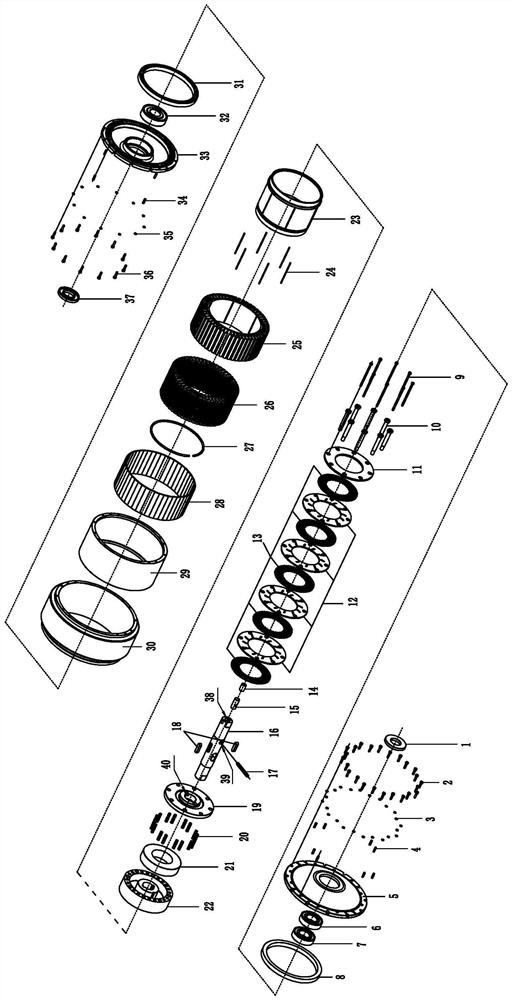
[0021] Below in conjunction with accompanying drawing, the present invention will be further described with specific embodiment, see figure 1 —3:

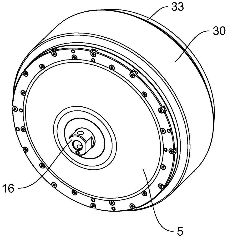
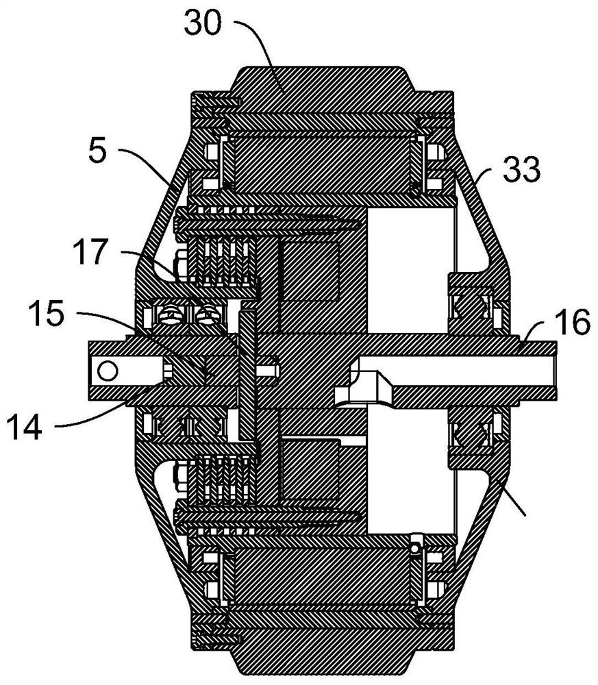
[0022] A high-torque brake hub motor, including a motor stator 25, a motor rotor 29, a motor housing and a motor shaft 16, the motor housing includes a roller 30 and end caps 1 and 2 33 arranged on both ends of the roller 30 , the inner side of the roller 30 is respectively provided with a motor rotor 29, a motor stator 25, assembly A and assembly B, and the relative position of the motor rotor 29 and the roller 30 is positioned by a straight pin-4 and fixed by a screw-2 to realize the motor The connection between the rotor 29 and the roller 30 ensures synchronous rotation. The motor shaft 16 passes through the motor rotor 29 and the roller 30 and the two ends are supported on the end cover one 5 and the end cover two 33 to keep relative movement through the motor winding 26 Assembled in the winding groove of the motor stator 25 t...


PUM


Abstract

The invention belongs to the technical field of electric carriers, and provides a large-torque brake hub motor. The motor comprises a motor stator, a motor rotor, a motor shell and a motor shaft, the motor shell comprises a roller, a first end cover and a second end cover, the first end cover and the second end cover are arranged on the two end faces of the roller, and the motor rotor, the motor stator, a component A and a component B are arranged on the inner side of the roller. The relative position of the motor rotor and the roller is positioned through a first cylindrical pin and fixed through a first screw, connection of the motor rotor and the roller is achieved, synchronous rotation is ensured, the motor shaft penetrates through the motor rotor and the roller, and the two ends of the motor shaft are supported on the first end cover and the second end cover to keep relative movement. A motor winding is assembled in a motor stator winding groove to form a hub motor excitation assembly, a magnetic steel sheet is assembled on the inner side face E face of an electronic rotor to form a hub motor permanent magnet, and when the motor winding is powered on, a rotating magnetic field is generated to drive the motor rotor to rotate to drive a roller to rotate to generate driving force; and the motor has the advantages that the advantages of a traditional manpower vehicle and a traditional motor-driven vehicle are combined, and the manpower and motor dual-drive mode is achieved.

Description

technical field [0001] The invention belongs to the technical field of electric transport vehicles, and in particular relates to a large-torque braking wheel hub motor. Background technique [0002] At present, the driving of electric pallet trucks and electric stackers on the market basically adopts the form of motor + gear box + electromagnetic brake, and the motor is directly connected with the gear box and electromagnetic brake. Individually adopt gearless hub direct drive motors that cannot realize high-torque electromagnetic brakes and manual release of electromagnetic brakes; [0003] There are several disadvantages in the above design: 1. The gears inside the gearbox will wear out after a long time of use and the noise will increase; 2. Due to the lubricating oil inside, there is a hidden danger of poor sealing and leakage; 3. Gearless hub direct drive Although the motor does not have the unique disadvantages of gear reduction drive, the gearless hub direct drive mo...

Claims


Application Information

Patent Timeline
Patent Type & Authority Applications(China)
IPC IPC(8): H02K1/12H02K1/27H02K5/04H02K7/102B60K7/00
CPCH02K1/12H02K1/2786H02K5/04H02K7/1023B60K7/0007Y02T10/64
Inventor 王江涛宋进元
Owner ZHEJIANG HAIMI MACHINERY CO LTD
Why Eureka
Try Eureka