
Grain boundary passivation method of perovskite solar cell

A solar cell and perovskite technology, applied in the field of solar cells, can solve the problems of perovskite thin film charge recombination, performance degradation of photovoltaic devices, etc., achieve reduction of internal defect state density, passivation of perovskite grain boundaries, and simple method easy-to-use effects

Active Publication Date: 2021-07-09
HEFEI UNIV OF TECH
View PDF9 Cites 0 Cited by
  • Summary
  • Abstract
  • Description
  • Claims
  • Application Information

AI Technical Summary

Problems solved by technology

Studies have shown that the grain boundary defects of perovskite films are the key factors restricting the photoelectric conversion efficiency and device stability of perovskite solar cells. Decline (L.D.Whalley et al, Journal of Chemical Physics.2017, 146, 220901)

Method used

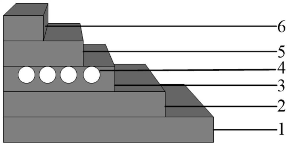
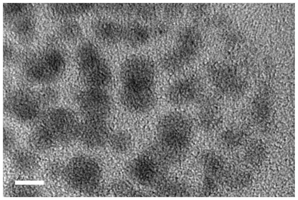
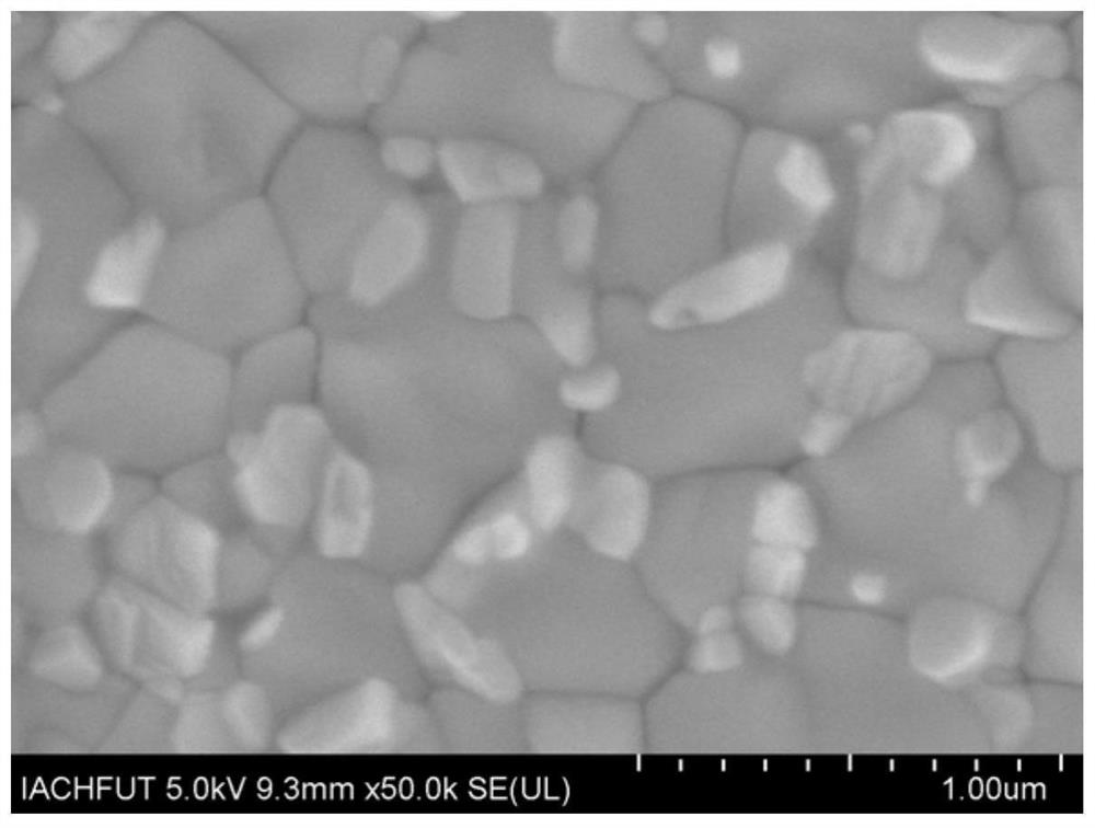

Image

  • Grain boundary passivation method of perovskite solar cell
  • Grain boundary passivation method of perovskite solar cell
  • Grain boundary passivation method of perovskite solar cell

Examples


Embodiment 1

[0028] 1. Cleaning of the conductive substrate: Use detergent, deionized water, acetone, ethanol, and isopropanol in sequence to ultrasonically clean the etched FTO glass for 15-20 minutes. After cleaning, dry the glass with a nitrogen gun. Then carry out UVO treatment for 25min~30min;

[0029] 2. TiO2 2 Preparation of the electron transport layer: Stir 125 μL diisopropoxybisacetylacetonate titanium solution and 1590 μL n-butanol for 1 h, then drop the mixed solution onto the FTO glass and rotate at 500 rpm for 3 s, then at 2000 rpm for 30 s, and finally Annealing at 135°C for 10 minutes, followed by sintering at 500°C for 30 minutes to obtain TiO 2 dense layer, the TiO 2 After the mesoporous film substrate was treated with ozone for 20 min, it was transferred to N 2 Ambient glove box;

[0030] 3. Preparation of perovskite layer: 100mL MAPbI 3 Perovskite precursor solution covered with TiO 2 On the electron transport layer, spin coating was performed at a rotation speed ...

Embodiment 2

[0037] 1. Cleaning of the conductive substrate: Use detergent, deionized water, acetone, ethanol, and isopropanol in sequence to ultrasonically clean the etched FTO glass for 15-20 minutes. After cleaning, dry the glass with a nitrogen gun. Then carry out UVO treatment for 25min~30min;

[0038] 2. Preparation of different electron transport layers: (1) TiO 2 : Stir 125 μL titanium diisopropoxybisacetylacetonate solution and 1590 μL n-butanol for 1 hour, then drop the mixed solution onto the FTO glass and rotate at 500 rpm for 3 seconds, then rotate at 2000 rpm for 30 seconds, and finally anneal at 135 ° C for 10 minutes. Then sintered at 500°C for 30min to obtain TiO 2 Dense layer; (2) SnO 2 : Will commercially use SnO 2 The hydrosol and deionized water were mixed and diluted according to the volume ratio of 1:7, and then spin-coated on the cleaned FTO at a speed of 3000rpm for 30s. After the spin coating is finished, place it on a heating platform and heat it at 150°C for...


PUM


Abstract

The invention discloses a grain boundary passivation method of a perovskite solar cell. The grain boundary passivation method comprises the following steps: firstly, synthesizing nanoscale C6H6NNaO6Pb quantum dots by utilizing a room-temperature solution reaction which is simple to operate; and uniformly dispersing the synthesized quantum dots in an anti-solvent in the process of preparing the perovskite thin film by a one-step method, so that the quantum dots are uniformly distributed in the perovskite thin film to realize perovskite grain boundary passivation. According to the invention, the perovskite grain boundary defect state density can be effectively reduced, and the quality of the perovskite thin film is improved, so that the efficient and stable perovskite solar cell is obtained. The preparation method is simple in process and low in cost, and has a good application prospect in the aspect of developing high-performance perovskite solar cells.

Description

technical field [0001] The invention belongs to the technical field of solar cells, and in particular relates to a grain boundary passivation method for perovskite solar cells. Background technique [0002] So far, solar cells can be mainly divided into three categories: first-generation crystalline silicon solar cells, second-generation compound thin-film solar cells, and third-generation new solar cells. Among them, perovskite solar cells, as the leader of new solar cells, have attracted extensive attention from researchers due to their advantages such as high light absorption coefficient, adjustable band gap, low cost, and simple preparation. In recent years, thanks to the active efforts of researchers in the fields of perovskite morphology control, battery structure, device physics, interface engineering, energy band engineering, etc., perovskite solar cells have achieved rapid development, and the photoelectric conversion efficiency of the device has increased by 2009 ...

Claims


Application Information

Patent Timeline
IPC IPC(8): H01L51/48H01L51/44
CPCH10K71/00H10K30/88Y02E10/549
Inventor 周儒李孝章胡棕源王欢万磊牛海红
Owner HEFEI UNIV OF TECH
Learn More