Material detection method, system and equipment based on LCR bridge and medium
A technology of material detection and electric bridge, which is applied in the direction of automatic test system, electronic circuit test, measuring electricity, etc., can solve the problems of low efficiency, measurement error, time-consuming and laborious, etc., so as to eliminate missed detection, reduce production cost, and reduce measurement effect of error
- Summary
- Abstract
- Description
- Claims
- Application Information
AI Technical Summary
Problems solved by technology
Method used
Image
Examples
Embodiment 1
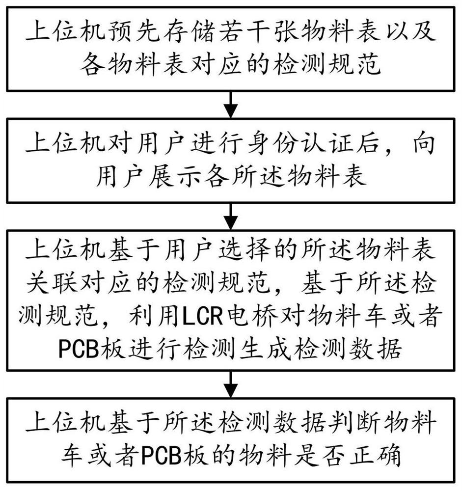
[0041] This embodiment provides a material detection method based on an LCR bridge, such as figure 1 and Figure 5 shown, including the following steps:
[0042] Step S10, the upper computer pre-stores several material tables and the corresponding testing specifications (testing configuration) of each material table; that is, each material truck of each factory line or each type of PCB board corresponds to a material table and a testing specification;
[0043] Step S20, after the host computer authenticates the user, it presents each material table to the user;
[0044] Step S30, based on the detection specification associated with the material list selected by the user, the host computer uses the LCR bridge to detect the material vehicle or PCB board to generate detection data based on the detection specification; the model of the LCR bridge is preferably TH2829; The upper computer communicates with the LCR bridge through RS232; the LCR bridge detects the PCB board through ...
Embodiment 2
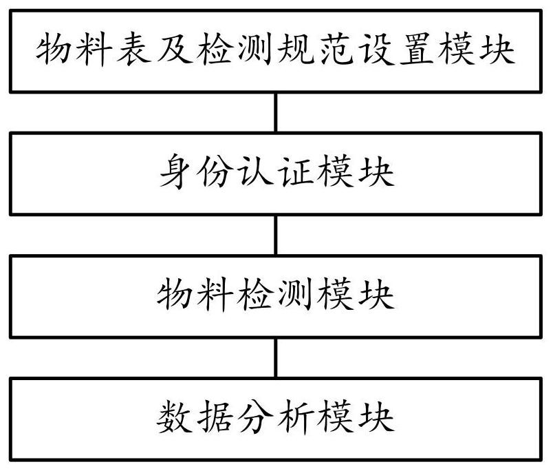
[0053] This embodiment provides a material detection system based on an LCR bridge, such as figure 2 and Figure 5 As shown, the following modules are included:
[0054] The material table and inspection specification setting module is used for the upper computer to pre-store several material sheets and the inspection specifications (test configuration) corresponding to each material sheet; that is, each material truck of each factory line or each type of PCB board corresponds to a material sheet and 1. Testing specifications;
[0055] The identity authentication module is used for the upper computer to display the material list to the user after the user is authenticated by the host computer;
[0056] The material detection module is used for the upper computer to detect the corresponding detection specification based on the material list selected by the user, and based on the detection specification, use the LCR bridge to detect the material truck or PCB board to generate...
Embodiment 3
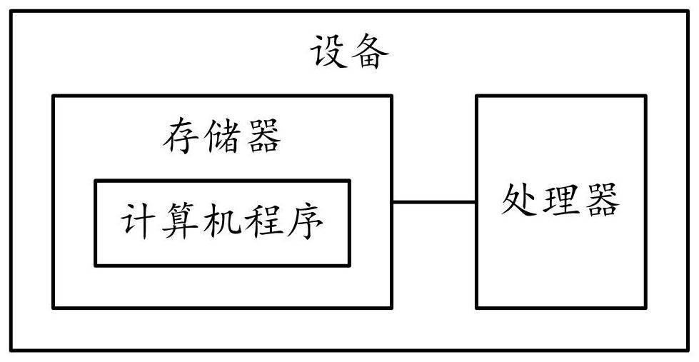
[0066] This embodiment provides a material detection device based on an LCR bridge, such as image 3 As shown, it includes a memory, a processor, and a computer program stored in the memory and operable on the processor. When the processor executes the computer program, any implementation manner in Embodiment 1 can be realized.
[0067] Since the electronic device introduced in this embodiment is the device used to implement the method in Embodiment 1 of this application, based on the method described in Embodiment 1 of this application, those skilled in the art can understand the electronic device of this embodiment. Specific implementation methods and various variations thereof, so how the electronic device implements the method in the embodiment of the present application will not be described in detail here. As long as a person skilled in the art implements the equipment used by the method in the embodiment of the present application, it all belongs to the protection scope...
PUM
 Abstract
Description
Claims
Application Information
 - R&D
- Intellectual Property
- Life Sciences
- Materials
- Tech Scout
- Unparalleled Data Quality
- Higher Quality Content
- 60% Fewer Hallucinations
Browse by: Latest US Patents, China's latest patents, Technical Efficacy Thesaurus, Application Domain, Technology Topic, Popular Technical Reports.
© 2025 PatSnap. All rights reserved.Legal|Privacy policy|Modern Slavery Act Transparency Statement|Sitemap|About US| Contact US: help@patsnap.com


