Compressor surface treatment method

A surface treatment and compressor technology, applied in metal material coating process, electrolytic coating, electrophoretic plating, etc., can solve the problem that the oxide layer is difficult to remove, the amount of alkali-resistant phosphating film is large, and the phosphating dead corner of the workpiece is sprayed. Incomplete and other problems, to achieve excellent salt spray performance, optimize and improve process conditions and the effect of equipment

Pending Publication Date: 2021-07-09
绵阳海立电器有限公司 +1
View PDF10 Cites 0 Cited by
  • Summary
  • Abstract
  • Description
  • Claims
  • Application Information

AI Technical Summary

Problems solved by technology

[0003] After the assembly line pendant mode of the compressor is increased from two hangers to three hangers, the production capacity is increased. However, the original spray phosphating process has problems such as incomplete spraying of workpiece phosphating dead spots, poor phosphating film formation, and matching with cathodic electrophoresis. The amount of phosphating film that is resistant to alkali dissolution is large, which leads to problems such as salt spray resistance that cannot meet the requirement that the peeling width of one side is less than 5mm
[0004] At the same time, if the spray phosphating process is used, there will be a lot of phosphating slag in the spray area and serious blockage
The slag pressing effect of the sediment tank is not good, the heat loss of the hot water tank is large, the heat is insufficient, and the film formation of the phosphating treatment is not complete, and the phosphating film will be uneven.
[0005] In summary, the oxidation layer after circular wave heating is difficult to remove in the compressor industry, the existing process of phosphating and film formation is poor, and the matching process and equipment basically cannot meet the salt spray resistance performance requirements and other related requirements of the compressor.

Method used

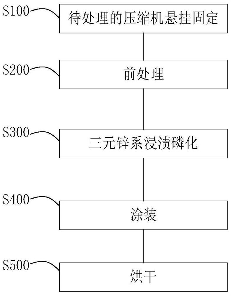

Image

  • Compressor surface treatment method
  • Compressor surface treatment method
  • Compressor surface treatment method

Examples


Embodiment Construction

[0030] Example embodiments will now be described more fully with reference to the accompanying drawings. Example embodiments may, however, be embodied in many forms and should not be construed as limited to the examples set forth herein; rather, these embodiments are provided so that this disclosure will be thorough and complete and will fully convey the concept of example embodiments to those skilled in the art. The described features, structures, or characteristics may be combined in any suitable manner in one or more embodiments.

[0031] Furthermore, the drawings are merely schematic illustrations of the present disclosure and are not necessarily drawn to scale. The same reference numerals in the drawings denote the same or similar parts, and thus repeated descriptions thereof will be omitted. Some of the block diagrams shown in the drawings are functional entities and do not necessarily correspond to physically or logically separate entities.

[0032] figure 1 It is a...


PUM


Abstract

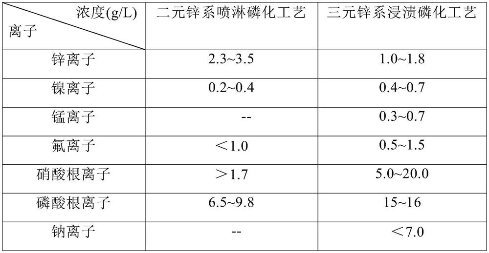
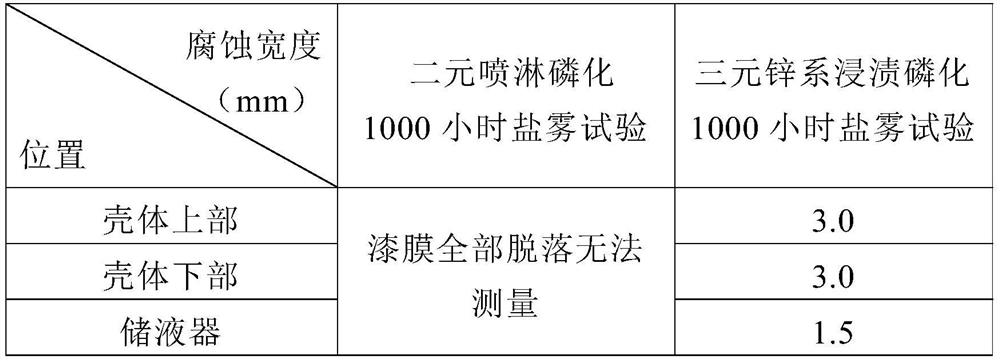
The invention provides a compressor surface treatment method. The method comprises the steps that a compressor to be treated is suspended and fixed; a pretreatment procedure is executed, wherein the pretreatment procedure comprises a degreasing treatment procedure for removing oil stains on the surface of a shell of the compressor by using degreasing fluid and a surface conditioning treatment procedure; a dipping phosphating procedure is executed; an electrophoretic coating procedure is executed; and a drying procedure is executed. According to the compressor surface treatment method, an original spraying phosphating process of the compressor is replaced with the dipping phosphating process, the problem that a compact oxide layer formed on the surface of the shell due to a hot jacket process is difficult to remove is effectively solved, a phosphating film formed through dipping is more compact, and by combining the electrophoretic coating process, a formed compressor surface paint film has better salt spray resistance.

Description

technical field [0001] The invention relates to the field of compressor surface treatment, in particular to a compressor surface treatment method. Background technique [0002] During the general assembly process of the compressor surface, the shell and the motor are assembled by heat-shrinking. During the heat-shrinking process, the shell is usually heated to 330°C to 360°C by high-frequency waves. At this time, dense oxidation will appear on the surface of the shell. The oxide layer is a blue, dark blue, dark purple coating, and this oxide layer on the surface is difficult to remove. [0003] After the assembly line pendant mode of the compressor is increased from two hangers to three hangers, the production capacity is increased. However, the original spray phosphating process has problems such as incomplete spraying of workpiece phosphating dead spots, poor phosphating film formation, and matching with cathodic electrophoresis. The amount of alkali-resistant leaching ph...

Claims


Application Information

Patent Timeline
IPC IPC(8): C23C22/73C23C22/78C25D13/12
CPCC23C22/73C23C22/78C25D13/12
Inventor 岳小琳郁冲沈梦琦
Owner 绵阳海立电器有限公司
Why Eureka
Try Eureka