Hydraulic locking knife holder

A hydraulic type, tool holder technology, applied in metal processing and other directions, can solve the problems of reducing precision and enhancing labor intensity, and achieve the effect of improving cutting accuracy, enhancing labor intensity and improving work efficiency

Pending Publication Date: 2021-07-09
南京精锋制刀有限公司
View PDF0 Cites 0 Cited by
  • Summary
  • Abstract
  • Description
  • Claims
  • Application Information

AI Technical Summary

Problems solved by technology

[0005] In view of the problems existing in the prior art, the purpose of the present invention is to provide a hydraulic locking tool holder, which has the advantages of improving work efficiency, saving costs, reducing labor intensity, and improving cutting accuracy, and solves the problems currently used by all steel mills. The device for fixing the slitting knife is basically a spacer and a rubber ring to control the width of the slitting. However, a large number of spacers and rubber rings are required for slitting and cutting metal sheets of different thicknesses and widths, which reduces the accuracy and enhances the The problem of labor intensity

Method used


Image

  • Hydraulic locking knife holder
  • Hydraulic locking knife holder
  • Hydraulic locking knife holder

Examples


Embodiment 2

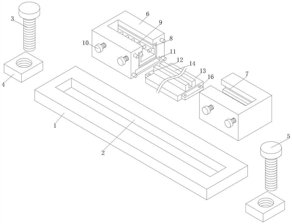
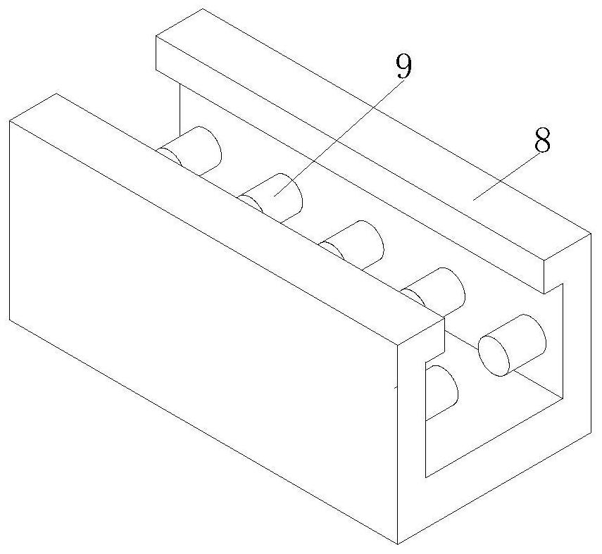
[0028] The hydraulic locking tool of the present embodiment is based on the first embodiment, and the different and improvements are in that the two bottom plate 1 has a slot 11, and the inner cavity activity of the slot 11 is connected. The socket 12, the socket 12 is fixed from one side of the slot 11 fixed to the fixing plate 13, and the top portion of the fixing plate 13 is fixedly coupled with a fixed seat 14, and the locking plate 4 is made of a metal material.

[0029] On the basis of the use of the first example, when the two tool holders 6 are separated, the fixed plate 13 of different lengths can be selected by the distance between the two blade body 6, and then the front and rear positions of the fixed plate 13 can be The socket 12 is inserted into the inner cavity of the slot 11, and the cutter is supported to prevent damage to the cutter.

Embodiment 3

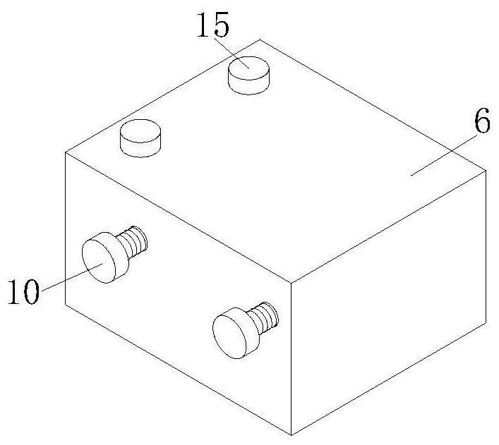
[0031] The hydraulic locking tool of the present embodiment is based on the second embodiment, and the different and improvement is that both both sides of the bottom of the blade body 6 are threaded with a locking bolt 15, and one end of the locking bolt 15 runs through The inner cavity of the slot 11 is threaded with the slot 11, and there is a restricted hole 16 on both sides of the top of the socket 12.

[0032] On the basis of the use of the second embodiment, when the insertion block 12 is inserted into the inner cavity of the slot 11, the locking bolt 15 is threaded with the slot 11, and the socket 12 is fixed, The fixing plate 13 is fixed to the fixed plate 13, thereby enhancing the stability of the two cutting body 6 connections.

Embodiment 4

[0034] The hydraulic locking tool of the present embodiment is based on the third embodiment, and the four angles of the bottom plate 1 are fixed by the side of the bottom plate 1, and the bottom plate 1 is fixed to the center at the bottom of the bottom plate 1 The surface of the pad, and the surface of the guard is provided with a slider, and the front end and the rear end on both sides of the tool holder 6 are opened with the threaded holes used in conjunction with the pressure bolt 10.

[0035] On the basis of the use of the third embodiment, after the adjustment is completed, the connecting bolt is inserted into the threaded hole of the device, then rotates the bolt, and lock the bottom plate 1 and the device, where the protective pad is used to enhance the backplane 1. Protectiveness.


PUM


Abstract

The invention discloses a hydraulic locking knife holder. The hydraulic locking knife holder comprises a bottom plate, a limiting groove is formed in the top of the bottom plate, an inner cavity of the limiting groove is movably connected with threaded rods, the bottoms of the surfaces of the threaded rods are in threaded connection with locking plates, and the tops of the threaded rods are fixedly connected with connecting blocks. According to the knife holder, the effect of limiting and supporting knife holder bodies is achieved through the bottom plate, the effect of facilitating widening adjustment on the knife holder bodies is achieved through the limiting groove, the effect of limiting and fixing the knife holder bodies is achieved through the threaded rods and the locking plates, the effect of placing and fixing clamping seats is achieved through grooves, the effect of limiting and fixing a cutting knife is achieved by means of bolt cores, the effect of pressing the clamping seats is achieved through pressure bolts, the purposes of improving the working efficiency, saving the cost, reducing the labor intensity and improving the cutting precision are achieved, the creativity and usability of the hydraulic locking knife holder are improved, and the use experience of a user is enhanced.

Description

Technical field [0001] The present invention relates to the technical field of slit cutting machine, and is specifically a hydraulic locking tool. Background technique [0002] The slitting machine is the printed, post-printing equipment, which is used in various thin materials such as a large volume of paper, film, nonwoven fabric, aluminum foil, mica belt, etc., is often used in papermaking machinery and printing packaging machinery. The magnetic powder clutch speed of the slitting machine cannot be high, because it is easy to cause high speed friction of magnetic powder during operation, produce high temperature, shorten its life, and calm down, so that the machine is blocked, which gives a very serious consequence to production. The production efficiency is affected. It is now used to control the control of the winding motor, so that the magnetic powder motor is controlled by the variable frequency motor control, and there is no high temperature. [0003] At present, the prod...

Claims


Application Information

Patent Timeline
IPC IPC(8): B26D7/26
CPCB26D7/2614B26D7/2628
Inventor 武舒平武晓东
Owner 南京精锋制刀有限公司
Why Eureka
Try Eureka