
Optical fiber strength testing method

A test method and optical fiber technology, applied in the direction of strength characteristics, the use of stable tension/pressure test material strength, measuring devices, etc., can solve problems such as easy loosening, insufficient fixing effect of optical fiber ends, and affecting test results

Active Publication Date: 2021-07-06
深圳市远昌电子有限公司
View PDF14 Cites 3 Cited by
  • Summary
  • Abstract
  • Description
  • Claims
  • Application Information

AI Technical Summary

Problems solved by technology

The traditional optical fiber strength testing device generally has a simple structure design, and the fixing effect on the end of the optical fiber is not good enough, and it is easy to loosen during the test process, thereby affecting the test results, so there are certain limitations.

Method used


Image

  • Optical fiber strength testing method
  • Optical fiber strength testing method
  • Optical fiber strength testing method

Examples


Embodiment 1

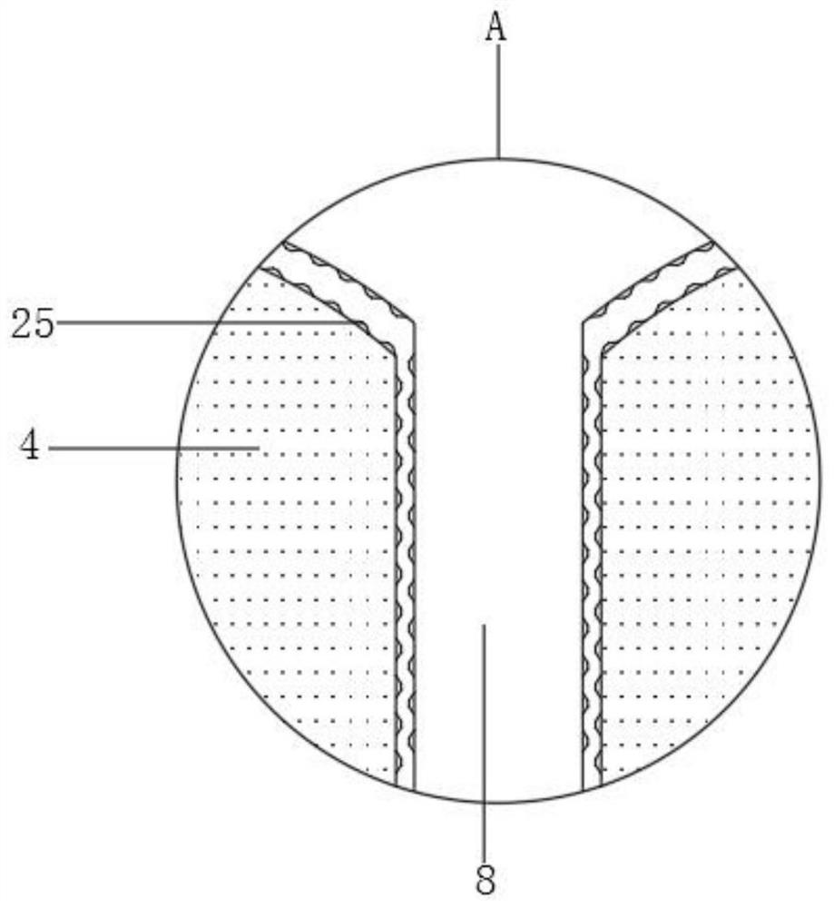
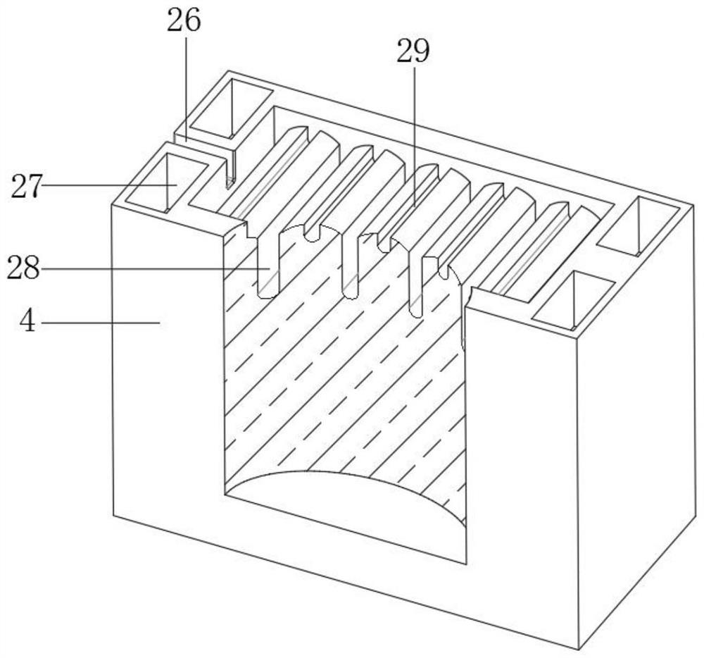
[0032] refer to Figure 1-6, an optical fiber testing device for strength, comprising a bottom plate 1 with four corners of the outer wall of the bottom welded with legs, side plates 2 are welded on both sides of the outer wall of the bottom plate 1, and the same platform is welded on the opposite side of the outer wall of the side plate 2 23, and the middle end of the platen 23 is fixedly installed with a limit end plate 36, and the two ends of the limit end plate 36 are respectively slidably connected with a fixed end block 15 and a pull block 4, and the top ends of the fixed end block 15 and the pull block 4 are both Equidistantly distributed arc bottom notches 28 and arc bottom short grooves 29 are provided, the arc bottom notches 28 and arc bottom short grooves 29 are alternately distributed, and the tops of the fixed end block 15 and the pulling block 4 are clamped with pressing blocks 13, and the bottom outer wall of the briquetting block 13 is respectively provided wit...

Embodiment 2

[0042] This embodiment discloses a method for testing the strength of an optical fiber, which includes the following steps: the operator places appropriate lengths of the two ends of the optical fiber to be tested on the fixed end block 15 and the top of the pulling block 4 respectively, and puts them into the corresponding pressing block 13, use the arc bottom socket 8 and the short pin 14 to match the arc bottom notch 28 and the arc bottom short groove 29 respectively, and fix the two ends of the optical fiber; The transmission effect of the tooth 19 and the driven tapered tooth 18 drives the threaded column rod 24 to rotate, so that the driving connecting plate 3 is used to push the pulling block 4, so that the optical fiber tends to be stretched straight; then, the operator controls and starts the electric telescopic rod 34 , push the cooling semi-copper tube 35 to close, and cooperate with the temperature sensor 11, use the semiconductor refrigerator 33 to keep the optical...


PUM


Abstract

The invention belongs to the technical field of optical fiber testing, and particularly relates to an optical fiber strength testing method which comprises a bottom plate with supporting legs welded to the four corners of the outer wall of the bottom, side plates welded to the outer walls of the two sides of the bottom plate, a table plate welded to the outer walls of the opposite sides of the side plates, and a limiting end plate fixedly installed at the middle end of the table plate, the two ends of the limiting end plate are slidably connected with a fixed end block and a pulling block correspondingly, arc-bottom notches and arc-bottom short grooves which are distributed at equal intervals are formed in the top end of the fixed end block and the top end of the pulling block correspondingly, and the arc-bottom notches and the arc-bottom short grooves are distributed in a staggered mode. According to the invention, through the arrangement of the arc bottom notch, the arc bottom short groove, the arc bottom insertion end and the short insertion pin, effective fixation processing of an optical fiber is realized in the mutual matching process; through the trapezoidal auxiliary blocks arranged on the sides, opposite to the arc bottom notch and the arc bottom short groove, of the arc bottom insertion end and the short insertion pin, the optical fiber fixing stability can be effectively improved, and therefore it is guaranteed that testing operation is conducted smoothly.

Description

technical field [0001] The invention relates to the technical field of optical fiber testing, in particular to a method for testing optical fiber strength. Background technique [0002] Optical fiber, short for optical fiber, is a fiber made of glass or plastic that acts as a means of light transmission. At the beginning of the development of polymer optical fiber, it was only used for the control and decoration of automobile lighting. Mainly used in medicine, decoration, automobiles, ships, etc., mainly display components. In terms of communication and image transmission, the application of polymer optical fibers is increasing, and it is used in industry for light guides, display panels, signs, switch lighting adjustments, optical sensors, etc. As a mainstream way of broadband access, optical fiber has the advantages of large communication capacity, long relay distance, good confidentiality performance, strong adaptability, small size and light weight, wide source of raw ...

Claims


Application Information

Patent Timeline
IPC IPC(8): G01N3/18G01N3/06G01N3/02
CPCG01N3/02G01N3/06G01N3/068G01N3/18
Inventor 刘丛巍
Owner 深圳市远昌电子有限公司
Learn More