
Sampling device for water quality monitoring

A sampling device, water quality monitoring technology, applied in sampling device, measuring device, sampling and other directions, can solve the problems of few functions, inability to take water samples, simple structure and so on

Inactive Publication Date: 2021-07-06
卢圆章
View PDF0 Cites 0 Cited by
  • Summary
  • Abstract
  • Description
  • Claims
  • Application Information

AI Technical Summary

Problems solved by technology

[0003] With the rapid development of the economy and the rapid increase in the degree of industrialization, a large amount of harmful substances are produced and discharged outdoors. Among them, the water pollution is the most serious, which greatly affects people's life and health. In order to effectively control sewage treatment and detection and prevention, relevant Personnel began to carry out large-scale sewage monitoring and treatment. The primary task of sewage monitoring and treatment is water sampling. When the existing water sampling equipment takes water samples at a specified depth in the flowing water flow, on the one hand, due to the impact of the water flow on the sampling device Impact, so that the sampling device moves with the water flow, it is inconvenient to accurately control the sampling settings to reach the depth of the water layer at the specified depth; secondly, because many existing sampling facilities are non-closed, it is impossible to take the water layer at the specified depth after entering the water. However, for some sampling devices that can take specified depth water layers, their structure is simple and their functions are few, and it is impossible to sample and analyze the sediment in the specified depth water layer during the process of taking water samples. Add additional devices, increase the workload and cost of sampling personnel

Method used


Image

  • Sampling device for water quality monitoring
  • Sampling device for water quality monitoring
  • Sampling device for water quality monitoring

Examples


Embodiment Construction

[0026] The following will clearly and completely describe the technical solutions in the embodiments of the present invention with reference to the accompanying drawings in the embodiments of the present invention. Obviously, the described embodiments are only some, not all, embodiments of the present invention. Based on the embodiments of the present invention, all other embodiments obtained by persons of ordinary skill in the art without making creative efforts belong to the protection scope of the present invention.

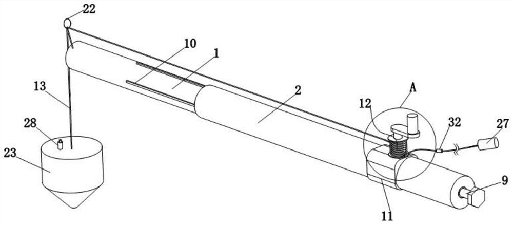
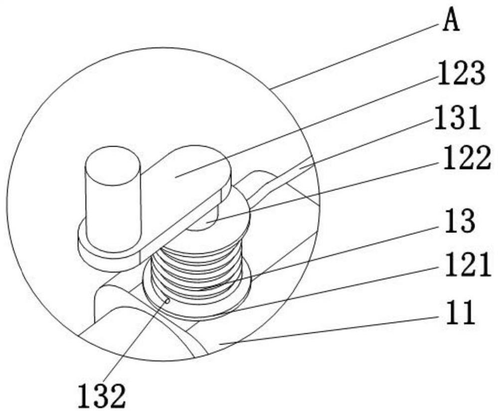
[0027] Such as Figure 1 to Figure 6As shown, the present invention provides a sampling device for water quality monitoring, including a telescopic cylinder 1, a support block 11 is sleeved on the telescopic cylinder 1, a winding device 12 is fixedly installed on the top of the support block 11, and a connecting wire is connected to the winding device 12 13. One end of the connection line 13 passes through the support ring 22 at the end of the telescopic tube ...


PUM


Abstract

A sampling device for water quality monitoring comprises a telescopic cylinder, the telescopic cylinder is sleeved with a winding device, and the winding device is connected with a connecting line and a sampling barrel; the sampling barrel comprises an uppermost threaded cover, a barrel part and a cone part, and a communicating valve communicated with the interior of the sampling barrel is arranged on the threaded cover; and a filter mechanism is arranged at the bottom of the cone part and comprises a filter pipe communicated with the cone part, a second filter screen is arranged above the filter pipe, a limiting device is arranged below the second filter screen, and a floating ball is arranged in the limiting device. According to the device, a water sample of a water layer with a specified depth can be collected, and a sediment sample in the water sample of the water layer with the specified depth can be collected, so that the functionality of the device is improved; and the problem that the sampling barrel moves along with water flow due to the impact of the water flow to the sampling device in the flowing water flow sampling process, and the sampling barrel cannot be accurately controlled to reach the depth of a water layer with a specified depth so as to collect a corresponding water sample is solved.

Description

technical field [0001] The invention belongs to the technical field of water quality monitoring, in particular to a sampling device for water quality monitoring. Background technique [0002] Water quality monitoring is the process of monitoring and measuring the types of pollutants in the water body, the concentration of various pollutants and the trend of change, and evaluating the water quality status. The monitoring scope is very wide, including unpolluted and polluted natural water (rivers, rivers, Lake, sea and groundwater) and various industrial drainage, etc.; the main monitoring items can be divided into two categories: one is a comprehensive indicator reflecting the water quality, such as temperature, color, turbidity, pH value, conductivity , suspended solids, dissolved oxygen, chemical oxygen demand and biochemical oxygen demand, etc.; the other category is some toxic substances, such as phenol, cyanide, arsenic, lead, chromium, cadmium, mercury and organic pesti...

Claims


Application Information

Patent Timeline
IPC IPC(8): G01N1/10G01N1/20
CPCG01N1/10G01N1/2035G01N2001/1025G01N2001/205
Inventor 卢圆章张冰苏建伟安明明毛晓宇姚鹏郑娇丽袁博李佳红王国重赵蓓蓓段华伟
Owner 卢圆章
Learn More