Tunnel section deformation monitoring method

A technology of deformation monitoring and cross-section, which is applied in the direction of measuring devices, instruments, and optical devices, etc., can solve the problems of dust accumulation on reflective targets, reducing the accuracy of monitoring results, etc.

Active Publication Date: 2021-07-06
CHINA COAL TECH & ENG GRP CHONGQING RES INST CO LTD
View PDF13 Cites 1 Cited by
  • Summary
  • Abstract
  • Description
  • Claims
  • Application Information

AI Technical Summary

Problems solved by technology

[0005] The present invention intends to provide a method for monitoring the deformation of the tunnel section to solve the problem of reducing the accuracy of the monitoring results after the reflection target accumulates dust

Method used


Image

  • Tunnel section deformation monitoring method
  • Tunnel section deformation monitoring method
  • Tunnel section deformation monitoring method

Examples


Embodiment 1

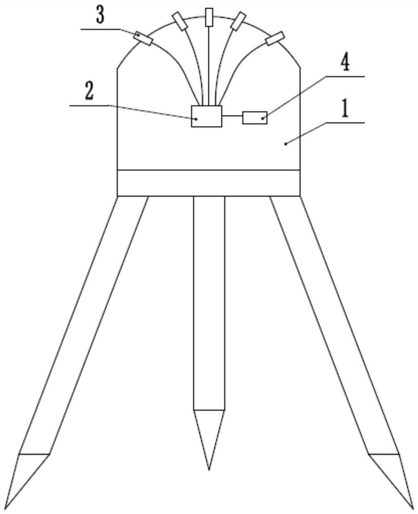
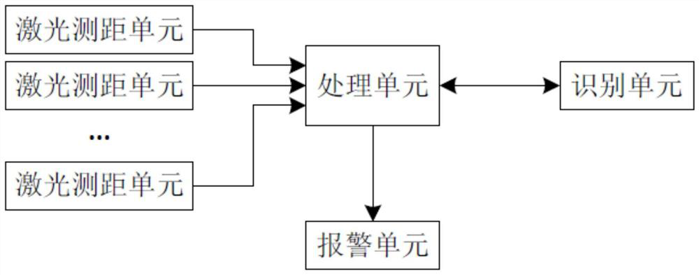
[0038] In order to realize the method, the first embodiment also discloses a tunnel section deformation monitoring device, such as figure 2 , image 3 and Figure 4 As shown, the mounting base 1 is included. The mounting base 1 is placed in the tunnel through a tripod for use. The mounting base 1 is equipped with an alarm unit, a processing unit 2, an identification unit 4 and a plurality of laser ranging units 3. The laser ranging unit 3 are evenly distributed on the same arc of the mounting base 1, and the laser distance measuring unit 3 can be an existing infrared laser transmitter.

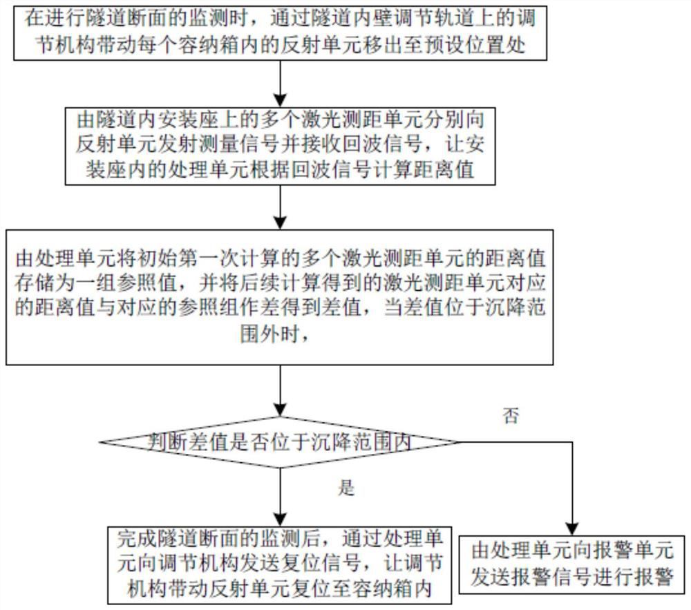
[0039] Such as Figure 5As shown, the laser ranging unit 3 is equipped with a plurality of reflection units 17 located on the inner wall of the tunnel, and also includes an adjustment track 5 located on the inner wall of the tunnel. The radial section of the adjustment track 5 is concave, and the adjustment track 5 can be screwed It is fixed to the inner wall of the tunnel, and the adjustm...

Embodiment 2

[0049] The difference from Embodiment 1 is that in step S3, the processing unit 2 judges whether the tunnel type is under construction. If the tunnel type is under construction, when the difference is outside the settlement range, the processing unit 2 will The size of the alarm unit sends alarm signals of different levels of information, and the detector in the alarm unit detects the human body signal in the tunnel. When the human body signal is detected, the controller of the alarm unit judges the level information of the alarm signal and controls the alarm. The power device located at the human body signal in the unit drives the alarm 11 to perform a level alarm of the illumination mode; specifically, the processing unit 2 judges whether the tunnel type is a built-up type, and if the tunnel type is a built-up type, multiple alarms 11 are set and The alarms 11 are installed along the inside and outside of the tunnel, and the controller controls all the alarms 11 to perform le...


PUM


Abstract

The invention relates to the field of solid deformation metering methods, in particular to a tunnel section deformation monitoring method, which comprises the following steps of S1, driving a reflecting unit in each accommodating box to move to a preset position through an adjusting mechanism on an adjusting rail on the inner wall of a tunnel; S2, enabling a plurality of laser ranging units in the tunnel to respectively emit measurement signals to the reflection units and receive echo signals, and enabling a processing unit in the mounting seat to calculate a distance value according to the echo signals; S3, storing the distance values, calculated for the first time, of the multiple laser ranging units as a set of reference values, obtaining difference values from the distance values and the corresponding reference sets, enabling a processing unit to judge whether the difference values are within a settlement range or not, and when the difference values are out of the settlement range, enabling the processing unit to send an alarm signal to an alarm unit to give an alarm; and S4, after monitoring of the tunnel section is completed, enabling the adjusting mechanism to drive the reflection unit to reset into the containing box. According to the invention, the measurement efficiency and the distance value comparability are improved.

Description

technical field [0001] The invention relates to the field of solid deformation measurement methods, in particular to a tunnel section deformation monitoring method. Background technique [0002] The data obtained from the tunnel deformation monitoring can be used as the basis for summarizing the deformation laws of the tunnel structure, as well as providing a basis for the maintenance of the tunnel structure to ensure the safe passage of vehicles or pedestrians. At present, tunnel deformation monitoring is done by pasting reflective sheets on the inner wall of the tunnel that need to be monitored, and then using a total station for monitoring. It is difficult to guarantee real-time monitoring. [0003] Aiming at the real-time problem of total station monitoring, the patent publication No. CN108801170A discloses a tunnel deformation monitoring system, which includes: a laser range finder, which is arranged on the side wall of the horizontal maximum width of the tunnel for Me...

Claims


Application Information

Patent Timeline
Patent Type & Authority Applications(China)
IPC IPC(8): G01B11/16
CPCG01B11/16
Inventor 张二锋雷凯利肖勇王圣龙
Owner CHINA COAL TECH & ENG GRP CHONGQING RES INST CO LTD
Why Eureka
Try Eureka