
Printing auxiliary equipment capable of controlling ink outlet amount through rotating speed and based on magnetic principle

A technology of speed control and auxiliary equipment, which is applied in the direction of printing, printing machines, general parts of printing machinery, etc. It can solve the problems that the ink output cannot be kept up in time, the ink cannot be used reasonably, and the printing quality of the equipment is affected.

Inactive Publication Date: 2021-07-06
卞业宏
View PDF10 Cites 2 Cited by
  • Summary
  • Abstract
  • Description
  • Claims
  • Application Information

AI Technical Summary

Problems solved by technology

[0003] However, when the existing equipment is printing on the packaging bag, the printing speed becomes faster, and the output of the ink cannot keep up with it in time, which may affect the printing quality of the equipment, and at the same time, the ink cannot be used reasonably, so that the energy saving cannot be achieved well. effect, and the surface of the packaging bag before and after printing cannot be well treated, which may affect the appearance of the packaging bag; therefore, those skilled in the art provide a printing auxiliary device that controls the amount of ink output based on the rotational speed of the magnetic principle. To solve the problems raised in the above-mentioned background technology

Method used


Image

  • Printing auxiliary equipment capable of controlling ink outlet amount through rotating speed and based on magnetic principle
  • Printing auxiliary equipment capable of controlling ink outlet amount through rotating speed and based on magnetic principle
  • Printing auxiliary equipment capable of controlling ink outlet amount through rotating speed and based on magnetic principle

Examples


Embodiment Construction

[0020] The following will clearly and completely describe the technical solutions in the embodiments of the present invention with reference to the accompanying drawings in the embodiments of the present invention. Obviously, the described embodiments are only some, not all, embodiments of the present invention. Based on the embodiments of the present invention, all other embodiments obtained by persons of ordinary skill in the art without making creative efforts belong to the protection scope of the present invention.

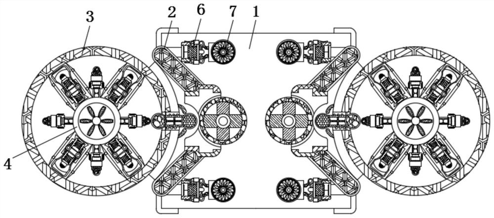
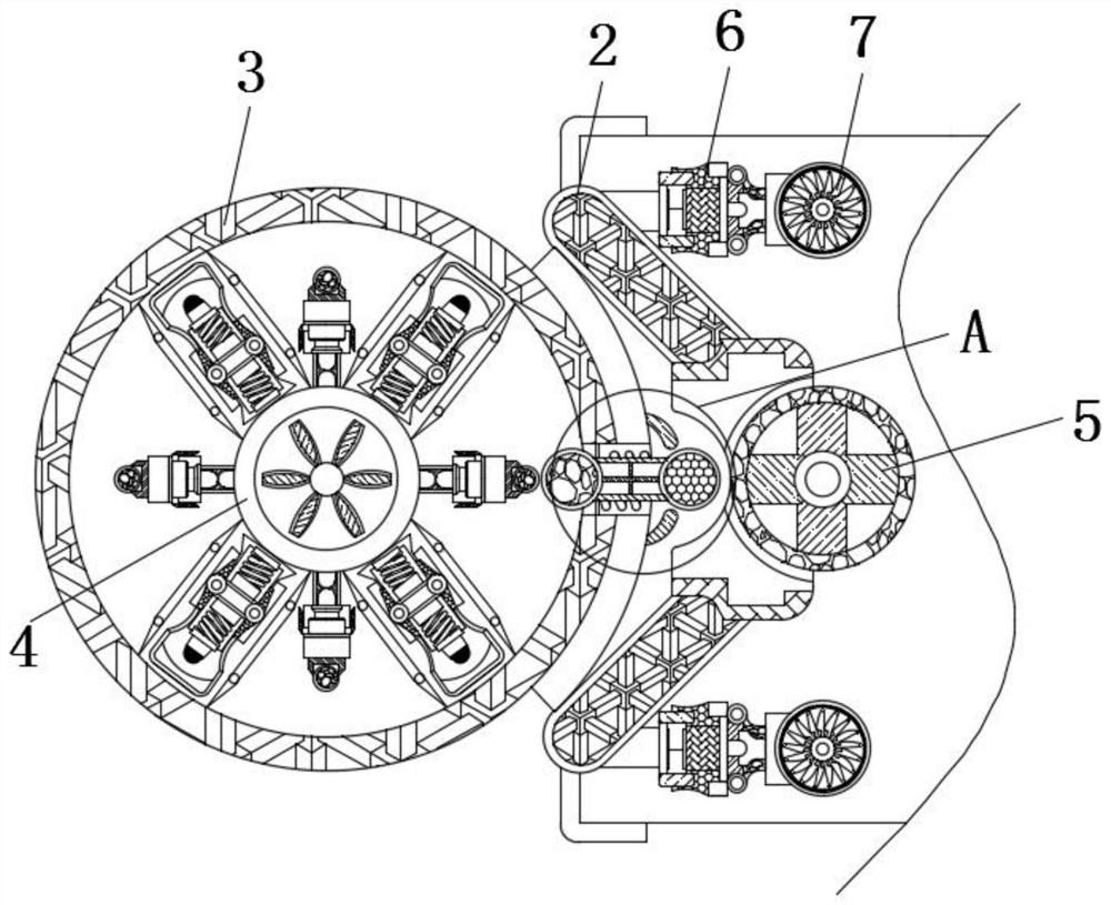
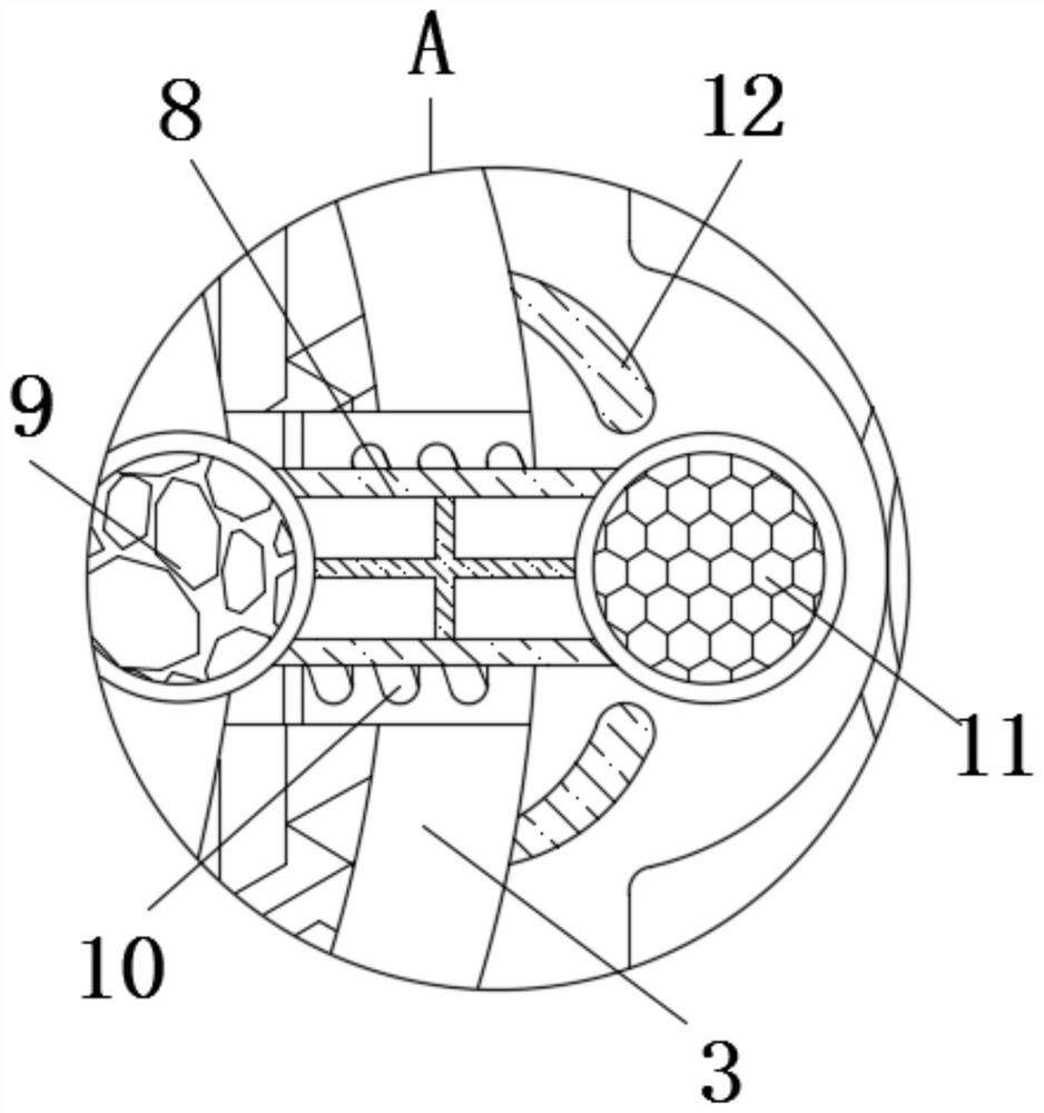
[0021] see Figure 1-5 , a printing auxiliary device based on the magnetic principle to control the amount of ink output by rotating speed, comprising a printing processing frame 1, a positioning frame 2 is fixedly connected to the inside of the printing processing frame 1, and an ink bucket 3 is fixedly connected to the left side of the positioning frame 2, The inside of the ink barrel 3 is a cavity, and the inside of the right side of the ink barrel 3 is pro...


PUM


Abstract

The invention relates to the technical field of printing auxiliary equipment for packaging bags, in particular to printing auxiliary equipment for controlling the ink outlet amount through the rotating speed and based on the magnetic principle. The printing auxiliary equipment comprises a printing processing frame, a positioning frame is fixedly connected to the interior of the printing processing frame, an ink barrel is fixedly connected to the left side surface of the positioning frame, a driven rotating wheel is rotationally connected to the center of the interior of the ink barrel, a printing roller is rotationally connected to the interior of the right side surface of the positioning frame, a fixing rod is fixedly connected to the right side surface of the positioning frame, and a blowing fan is rotationally connected to the interior of the right side surface of the fixing rod. A first magnet ball gets closer to a magnet ball along with increase of the speed, so that the first magnet ball extends the attraction force to the magnet ball, the distance between the first magnet ball and the magnet ball is increased, meanwhile, the attraction time of the first magnet ball to the magnet ball is shortened, the ink outlet amount can be well controlled according to the printing speed, and the reasonable use effect is achieved.

Description

technical field [0001] The invention relates to the technical field of printing auxiliary equipment for packaging bags, in particular to an auxiliary printing equipment that controls the amount of ink output by rotating speed based on the magnetic principle. Background technique [0002] Packaging bags refer to bags used to pack various supplies, making the goods convenient to transport and store during the production and distribution process. Widely used in daily life and industrial production, the commodity nature of packaging itself is becoming more and more significant. It has become a special product that is no longer attached to commodity production, and a widely used product that all commodities cannot do without. , and packaging bags will use printing equipment during the production process. [0003] However, when the existing equipment is printing on the packaging bag, the printing speed becomes faster, and the output of the ink cannot keep up with it in time, whic...

Claims


Application Information

Patent Timeline
IPC IPC(8): B41F31/02B41F23/00B41F23/04
CPCB41F31/02B41F23/00B41F23/04
Inventor 卞业宏
Owner 卞业宏
Learn More