
Automatic production line for assembling automobile fuel pump and using method of automatic production line

An automated production line, fuel pump technology, applied in vehicle parts, transportation and packaging, metal processing, etc., can solve problems such as inability to guarantee production efficiency and hidden dangers to human safety

Pending Publication Date: 2021-07-06
李建国
View PDF0 Cites 3 Cited by
  • Summary
  • Abstract
  • Description
  • Claims
  • Application Information

AI Technical Summary

Problems solved by technology

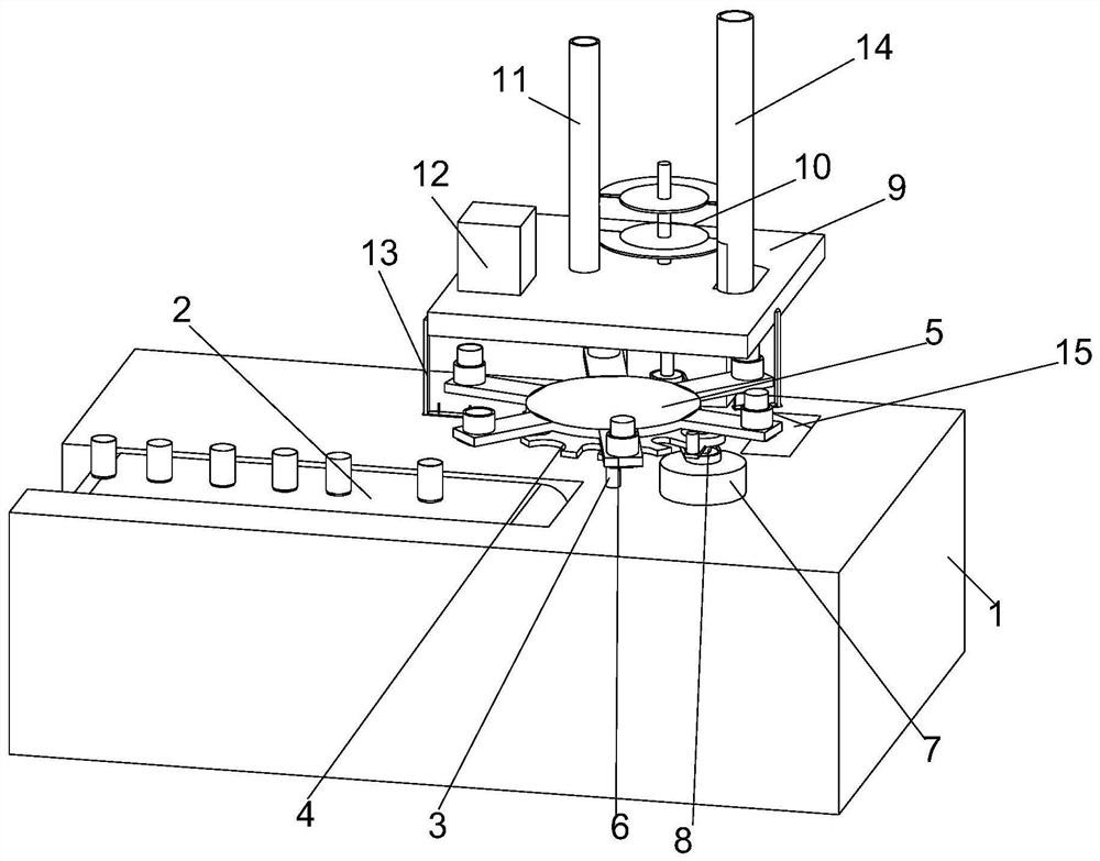
In the production and assembly of existing fuel pumps, some steps are still manually assembled, such as the motor assembly in the rotor, or the metal tube is put on the motor assembly manually, and then stamped with stamping equipment, so that the metal tube can be firmly It is firmly set on the motor assembly, because manual assembly not only cannot guarantee production efficiency, but also when using stamping equipment for stamping, manual operation will also cause safety hazards to the human body. In order to improve production efficiency and ensure the safety of staff, the industry To reduce the occurrence of safety accidents, it is particularly important to propose an automated production line for automotive fuel pump assembly. In view of this, we propose an automated production line for automotive fuel pump assembly and its use method

Method used


Image

  • Automatic production line for assembling automobile fuel pump and using method of automatic production line
  • Automatic production line for assembling automobile fuel pump and using method of automatic production line
  • Automatic production line for assembling automobile fuel pump and using method of automatic production line

Examples


Embodiment Construction

[0035] In describing the present invention, it should be understood that the terms "center", "longitudinal", "transverse", "length", "width", "thickness", "upper", "lower", "front", " Orientation indicated by rear, left, right, vertical, horizontal, top, bottom, inside, outside, clockwise, counterclockwise, etc. The positional relationship is based on the orientation or positional relationship shown in the drawings, and is only for the convenience of describing the present invention and simplifying the description, rather than indicating or implying that the referred device or element must have a specific orientation, be constructed and operated in a specific orientation, Therefore, it should not be construed as limiting the invention.

[0036] In the description of the present invention, "plurality" means two or more, unless otherwise specifically defined.

[0037] In the description of the present invention, it should be noted that, unless otherwise specified and limited, t...


PUM


Abstract

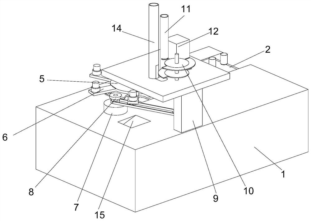
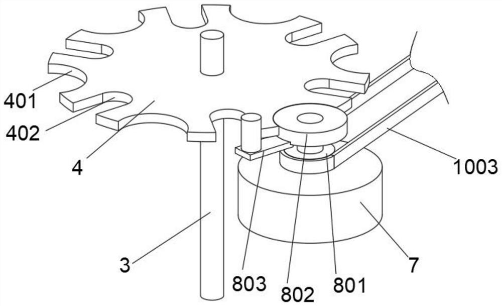
The invention discloses an automatic production line for assembling an automobile fuel pump and a using method of the automatic production line, and belongs to the technical field of automobile part assembling equipment. The automatic production line for assembling the automobile fuel pump comprises an equipment plate, a conveying belt is arranged on one side of the top face of the equipment plate, a motor is fixedly arranged on one side of a rotating shaft, the output end of the motor is sleeved with a transmission assembly, an equipment frame is arranged above the equipment plate, a feeding assembly and a sleeve A are arranged on the top face of the equipment frame in a penetrating mode, stamping equipment is arranged on one side of the top face of the equipment frame in a penetrating mode, and adjusting frames are fixedly connected to the two sides of the equipment frame. The transmission assembly is arranged, the motor is used for driving a rotary disc to rotate, then an arc-shaped partition plate on the upper side can enter a limiting groove in the upper side to block a metal pipe on the upper side, and therefore the intermittent feeding effect is achieved, and then a motor assembly sleeved with the metal pipe can move to the position below the stamping equipment, the stamping equipment is used for stamping, so that the situation that parts are manually placed below the stamping equipment is avoided, and potential safety hazards are avoided.

Description

technical field [0001] The invention relates to the technical field of assembly equipment for automobile parts, and more specifically, relates to an automatic production line for assembly of automobile fuel pumps and a method for using the same. Background technique [0002] As a part of auto parts, the main function of the fuel pump is to suck out the fuel from the fuel tank, pressurize it, and deliver it to the fuel supply pipe, and cooperate with the fuel pressure regulator to establish a certain fuel pressure. During the production and assembly process of the fuel pump, each station of the rear end cover assembly, stator assembly, single-machine assembly of sheet matching, single-machine assembly of pressure pump cover, final assembly and test degreasing assembly needs to be equipped with operators to ensure that the back-end Caps, electrode protection sleeves, rear end cover casings, magnets, spring clips, rotors, pump bodies, bearings, impellers and other components ca...

Claims


Application Information

Patent Timeline
Patent Type & Authority Applications(China)
IPC IPC(8): B23P19/02
CPCB23P19/001B23P19/02B23P2700/50
Inventor 李建国
Owner 李建国
Learn More