
Flexible circuit board chip mounter

A technology for flexible circuit boards and placement machines, which is used in mechanical equipment, printed circuits, printed circuit manufacturing, etc., can solve problems such as low work efficiency and defects, and achieve the effect of improving work efficiency, speed, and enhancing fixing effect.

Inactive Publication Date: 2021-06-29
胡煜
View PDF0 Cites 4 Cited by
  • Summary
  • Abstract
  • Description
  • Claims
  • Application Information

AI Technical Summary

Problems solved by technology

[0004] The purpose of the present invention is to provide a flexible circuit board placement machine, which enhances the fixing effect on the circuit board, reduces the possibility of its position shifting during the placement process, and improves the components in a certain extent. The accuracy in the placement process improves the qualified rate of the product. Through the five sets of cylinders and suction nozzles, the material can be continuously sucked and placed, which improves the continuity of the placement and the speed of the placement is faster. To a certain extent, the working efficiency of the patch is improved, the pressure on the circuit board during the patch process is reduced, the possibility of the circuit board being crushed is reduced, and the production cost is reduced to a certain extent, so as to solve the problems raised in the above-mentioned background technology. In some technologies, not only the work efficiency is low, but also mildew occurs due to the dampness of the single line, causing bad problems

Method used

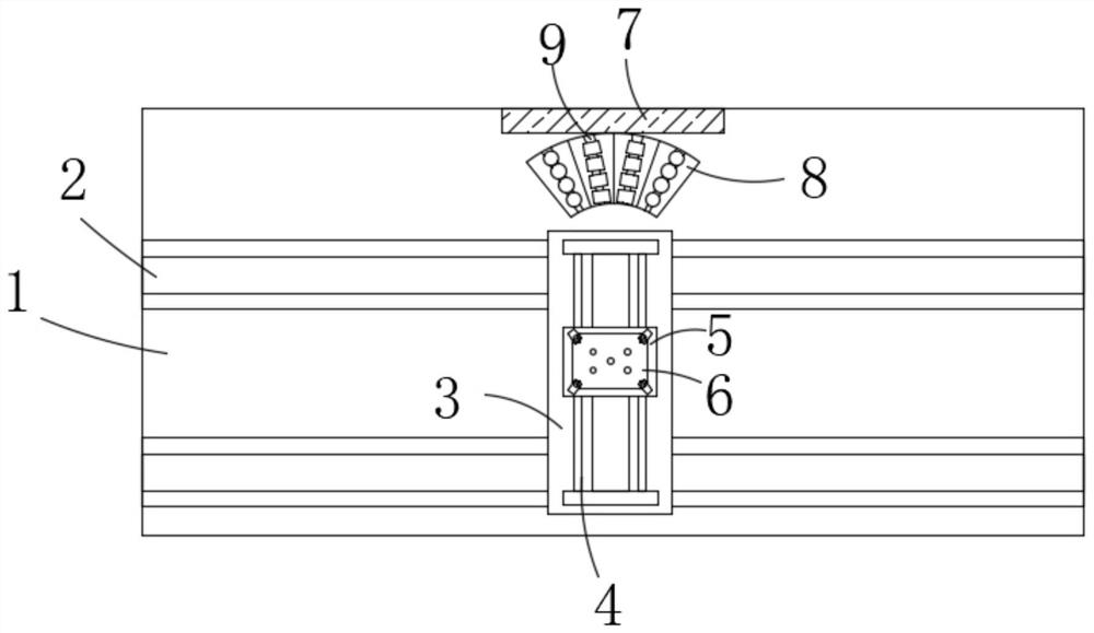
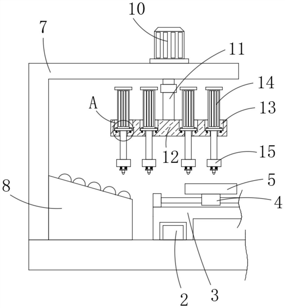
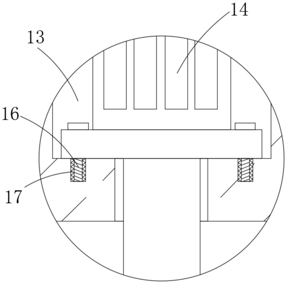

Image

  • Flexible circuit board chip mounter
  • Flexible circuit board chip mounter
  • Flexible circuit board chip mounter

Examples


Embodiment Construction

[0028] Next, the technical solutions in the embodiments of the present invention will be apparent from the embodiment of the present invention, and it is clearly described, and it is understood that the described embodiments are merely embodiments of the present invention, not all of the embodiments. DETAILED DESCRIPTION OF THE INVENTION The present invention is not intended to limit the invention. Based on the embodiments of the present invention, there are all other embodiments obtained without making creative labor without making creative labor premises.

[0029] The present invention provides Figure 1-8 A flexible circuit board aircraft, including a table 1, a table 1, and a slide rail 2 is fixed, and two sets of rail 2 are provided, and the sliding rail 2 is slid. 3, the slide 3 Set to a U-shaped slide, the end of the slide 3 is opened with two sets of chutes, and the slider 3 is located inside the chute, and the motor slide 4 is fixedly mounted on the slide 3, the sliding se...


PUM


Abstract

The invention discloses a flexible circuit board chip mounter which comprises a workbench, wherein a sliding rail is fixedly installed on the workbench, a sliding base is installed on the sliding rail in a sliding mode, an electric sliding table is fixedly installed on the sliding base, a carrier plate is fixedly installed on the sliding base of the electric sliding table, a groove is formed in the carrier plate, and a supporting column and a supporting block are arranged in the groove. According to the flexible circuit board chip mounter, the fixing effect of the circuit board is enhanced, the possibility of position deviation of the circuit board in the surface mounting process is reduced, the precision of the element in the surface mounting process is improved to a certain extent, the qualified rate of products is further improved, material suction and chip mounting can be continuously performed through five groups of air cylinders and suction nozzles, the chip mounting continuity is improved, the chip mounting speed is higher, the chip mounting working efficiency is improved to a certain extent, the pressure on a circuit board in the chip mounting process is reduced, the possibility that the circuit board is crushed is reduced, and the production cost is reduced to a certain extent.

Description

Technical field [0001] The invention belongs to the technical field of the postmaker, and is specifically involved in a flexible circuit board. Background technique [0002] The patch machine, also known as "mounting machine", "surface mount system", in the production line, it is configured after the dispensing machine or screen printing machine, is accurately placed by the mobile sticker One device on the PCB pad, the patch machine is divided into two manual and fully automated, is used to achieve high-speed, high precision and discharge, the entire SMI, the most critical and most complex equipment in production. The patch machine is SMT production to use a patch equipment, and the fully automatic patch machine is a high-precision automation equipment integrating computer control and collector electrical integration. The first is transmitted and carries tissue, drive system. , Positioning and compining the middle system, the mounting head, the feeder, the optical identification ...

Claims


Application Information

Patent Timeline
Patent Type & Authority Applications(China)
IPC IPC(8): H05K13/04H05K13/00H05K3/34F16F15/067
CPCF16F15/067H05K3/341H05K13/0069H05K13/046H05K13/0465H05K13/0409H05K13/041
Inventor 胡煜
Owner 胡煜
Learn More