
Split type water pump

A split type, water pump technology, applied in the field of refrigerator parts, can solve problems such as noise, impact, impeller imbalance, etc., to achieve the effect of avoiding noise, avoiding falling off, and reducing assembly errors

Pending Publication Date: 2021-06-29
JIANGSU KIND ELECTRIC CO LTD
View PDF0 Cites 0 Cited by
  • Summary
  • Abstract
  • Description
  • Claims
  • Application Information

AI Technical Summary

Problems solved by technology

[0003] When the existing split water pump is running, its impeller is prone to imbalance caused by manufacturing errors, which will cause it to collide in the pump body and generate noise

Method used


Image

  • Split type water pump
  • Split type water pump

Examples


Embodiment Construction

[0025] In order to make the purpose and technical solutions of the embodiments of the present invention more clear, the technical solutions of the embodiments of the present invention will be clearly and completely described below in conjunction with the drawings of the embodiments of the present invention. Apparently, the described embodiments are some, not all, embodiments of the present invention. Based on the described embodiments of the present invention, all other embodiments obtained by persons of ordinary skill in the art without creative efforts shall fall within the protection scope of the present invention.

[0026] Those skilled in the art can understand that, unless otherwise defined, all terms (including technical terms and scientific terms) used herein have the same meaning as commonly understood by those of ordinary skill in the art to which this invention belongs. It should also be understood that terms such as those defined in commonly used dictionaries shoul...


PUM


Abstract

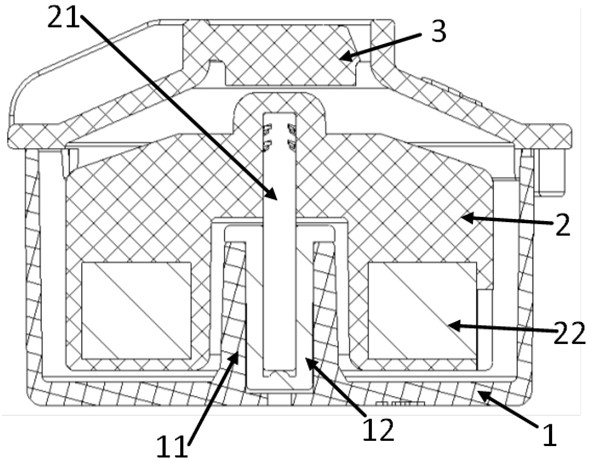
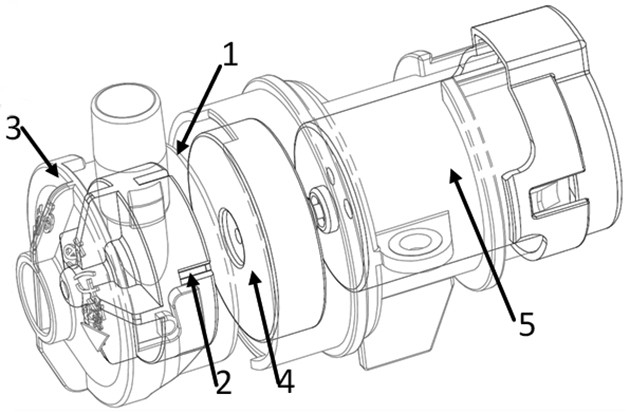
The invention provides a split type water pump. The split type water pump comprises a pump cover and a pump body lower shell which are connected with each other, and an impeller is arranged in a cavity formed between the pump cover and the pump body lower shell. According to the water pump, the impeller is installed on the lower shell of the pump body through the rotating shaft and is kept not in direct contact with the pump cover. Therefore, an upper fulcrum and a lower fulcrum of an original impeller can be reduced to be a single fulcrum which is only arranged at one end of the rotating shaft, so that the impeller and the pump cover are prevented from making contact and colliding, and noise is avoided. Meanwhile, according to the mounting mode that the rotating shaft is arranged between the pump body lower shell and the impeller, the rotating shaft can be prevented from falling off, assembly errors are reduced, and meanwhile it is guaranteed that the impeller has good dynamic balance performance in the high-speed rotating state.

Description

technical field [0001] The invention relates to the field of refrigerator components, in particular to a split water pump. Background technique [0002] The split type water pump consists of two parts: the pump body and the driving device. An accommodating cavity is formed inside the pump body, a water inlet and a pump outlet are provided outside the pump body, and an impeller is arranged in the accommodating cavity. After the liquid enters the accommodating cavity from the water inlet, it is pushed to be pumped out from the pump outlet by the rotation of the impeller. In order to drive the impeller, the impeller magnet is usually arranged inside the impeller, and the drive magnet and a drive motor which are attracted to each other are arranged in the drive device. The driving motor runs, and the output torque of the motor shaft drives the driving magnet to rotate synchronously, and the driving magnet is located close to the impeller, which can drive the impeller to rotate...

Claims


Application Information

Patent Timeline
IPC IPC(8): F04D13/06F04D13/02F04D29/22F04D29/66
CPCF04D13/06F04D13/024F04D29/2222F04D29/2261F04D29/669
Inventor 张炳圣李苗
Owner JIANGSU KIND ELECTRIC CO LTD
Learn More