a solar panel
A technology for solar panels and placement panels, applied in the field of solar panels, can solve problems such as inconvenient operator restraint and disassembly, and achieve the effects of reducing occupied space, reducing pressure, and reducing damage
- Summary
- Abstract
- Description
- Claims
- Application Information
AI Technical Summary
Problems solved by technology
Method used
Image
Examples
Embodiment 1
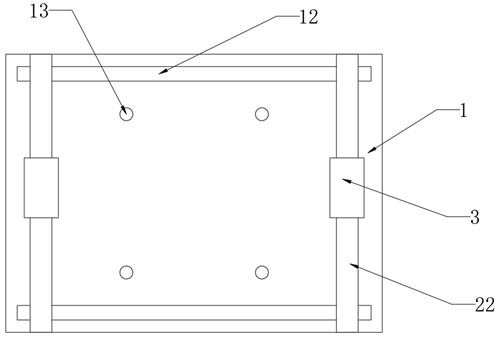
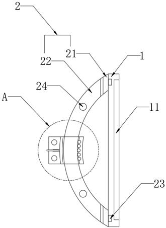
[0040] Embodiment 1, refer to figure 2 As shown, a solar panel includes an aluminum alloy placing plate 1 , a solar panel 11 is disposed inside the aluminum alloy placing plate 1 , and the aluminum alloy placing plate 1 wraps the surrounding and one side of the solar panel 11 . The aluminum alloy placement plate protects the solar panel.
[0041] refer to figure 2 As shown, two supporting plates 2 are symmetrically arranged on one side of the aluminum alloy placing plate 1 away from the solar panel 11 , and the vertical section of the supporting plates 2 is arc-shaped. The person carrying the person passes the arm through the space between the corresponding support plate 2 and the aluminum alloy placing plate 1 to easily and quickly carry the solar panel 11;
[0042] At the same time, the two support plates 2 act as support frames, which is convenient for the person carrying the solar panels 11 to move the solar panels 11 to the destination, and then quickly assemble the s...
Embodiment 2
[0058] Embodiment 2: The same parts of this embodiment and Embodiment 1 will not be repeated. The difference between this embodiment and Embodiment 1 is:
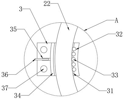
[0059] refer to image 3 The other side of the inner wall of the arc-shaped through hole 31 is provided with a plurality of arc grooves 32 , and balls 33 are arranged inside the plurality of arc grooves 32 , and the balls 33 form point contact with one side of the support plate 2 . The balls 33 form a rolling connection between the mounting block 3 and the support plate 2 , which facilitates the operator to move the mounting block 3 on the corresponding support plate 2 .
[0060] In the specific implementation process, when the operator moves the installation block 3, since the ball 33 is located between the support plate 2 and the arc-shaped through hole 31, rolling friction is formed between the arc-shaped through hole 31 and the support plate 2, which is convenient for the operator to quickly move and install Block 3. ...
Embodiment 3
[0061] Embodiment 3: The same parts of this embodiment and Embodiment 1 will not be repeated. The difference between this embodiment and Embodiment 1 is:
[0062] refer to image 3 , the side of the pressing block 34 away from the coil 35 is processed with anti-skid lines. The anti-skid pattern further strengthens the tightness between the pressing block 34 and the support plate 2 , so as to prevent the position of the mounting block 3 on the corresponding support plate 2 from being offset when being carried.
[0063] refer to image 3 , one end of the mounting block 3 between the support plate 2 and the aluminum alloy placing plate 1 is arc-shaped. The side of the installation block 3 in contact with the shoulder of the person carrying the person can be better buckled on the shoulder of the person carrying the person, so that the installation block 3 is not easily out of contact with the shoulder of the person carrying the person.
[0064] Specific implementation content: ...
PUM
 Abstract
Description
Claims
Application Information
 - R&D
- Intellectual Property
- Life Sciences
- Materials
- Tech Scout
- Unparalleled Data Quality
- Higher Quality Content
- 60% Fewer Hallucinations
Browse by: Latest US Patents, China's latest patents, Technical Efficacy Thesaurus, Application Domain, Technology Topic, Popular Technical Reports.
© 2025 PatSnap. All rights reserved.Legal|Privacy policy|Modern Slavery Act Transparency Statement|Sitemap|About US| Contact US: help@patsnap.com


