Phased-array antenna electrical performance compensation method and system based on temperature field reconstruction
A technology of phased array antenna and compensation method, which is applied in the direction of antenna, antenna array, circuit, etc.
- Summary
- Abstract
- Description
- Claims
- Application Information
AI Technical Summary
Problems solved by technology
Method used
Image
Examples
Embodiment 1
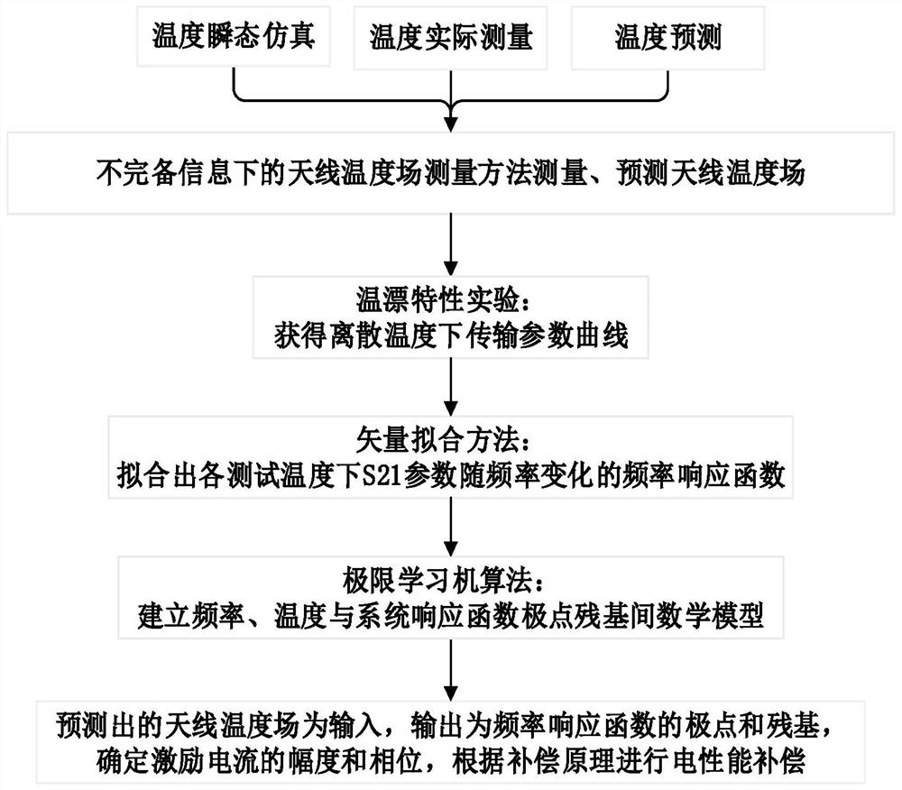
[0063] Such as figure 1 As shown, this embodiment provides a technical solution: a phased array antenna electrical performance compensation method based on temperature field reconstruction, including the following:
[0064] Step (1): Determine the electrical performance compensation principle of the phased array antenna:
[0065] The ideal electrical performance function of an active phased array antenna can be expressed as:
[0066]
[0067] Wherein, N is the unit number of antenna array; is the excitation current of the nth antenna element, where A n with Indicates the amplitude and phase of the unit excitation current; f n (θ,φ) is the active element pattern of the nth antenna element; the vector is the vector radius from the coordinate origin to the center of the nth antenna element, where x n ,y n ,z n Indicates the location coordinates of the cell center; from the coordinate origin to The unit vector of the viewing direction; k = 2π / λ denotes the wave c...
Embodiment 2
[0093] This embodiment provides a technical solution: a phased array antenna electrical performance compensation method based on temperature field reconstruction, including the following:
[0094] 1. Experimental content
[0095] In this embodiment, the power amplifier used in the temperature drift characteristic experiment of the power amplifier is the HMC952ALP5GE chip produced by Hittite Company. In the corresponding parameter manual, the normal operating frequency band of the chip is 8-12GHz, and the PA implementation sample The substrate material of the test circuit board is RogersRT / duroid4350, the dielectric constant ε r =2.2, the dielectric loss tangent tanδ=0.0002, the radio frequency transmission line adopts the form of coplanar waveguide.
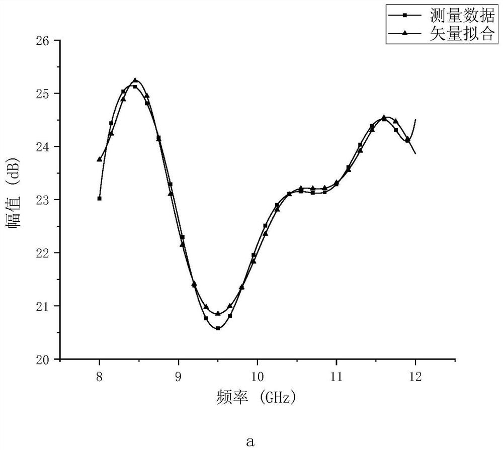
[0096] During the whole implementation process, by changing the temperature of the high and low temperature box, the image of the amplitude of the transmission coefficient S21 (forward transmission coefficient, ie gain) changing...
Embodiment 3
[0102] Based on Embodiment 2, in this embodiment, the center frequency of the antenna used during the experiment is 10 GHz; the antenna is designed according to the above-mentioned center frequency, and according to the results of the temperature drift characteristic experiment on the power amplifier device, it is determined by vector fitting and extreme learning machine algorithm The mechanism model of the influence of temperature on the amplitude and phase is established, and the simulation model of the antenna is 8×8 elements, such as Figure 4 As shown, it is the temperature distribution of the antenna unit in Embodiment 1, and the amplitude and phase to be compensated are calculated according to the proposed method for calculating electrical performance compensation, and the final compensation result is as follows Image 6 shown.
PUM
 Abstract
Description
Claims
Application Information
 - Generate Ideas
- Intellectual Property
- Life Sciences
- Materials
- Tech Scout
- Unparalleled Data Quality
- Higher Quality Content
- 60% Fewer Hallucinations
Browse by: Latest US Patents, China's latest patents, Technical Efficacy Thesaurus, Application Domain, Technology Topic, Popular Technical Reports.
© 2025 PatSnap. All rights reserved.Legal|Privacy policy|Modern Slavery Act Transparency Statement|Sitemap|About US| Contact US: help@patsnap.com


