Support-free prefabricated floor slab with brackets
A floor slab and corbel technology, applied in the field of prefabricated building structural components, can solve the problems of increasing construction costs, affecting construction efficiency, limiting construction space, etc., and achieves the effects of convenient installation, improving construction efficiency, and shortening the construction period
- Summary
- Abstract
- Description
- Claims
- Application Information
AI Technical Summary
Problems solved by technology
Method used
Image
Examples
Embodiment 1
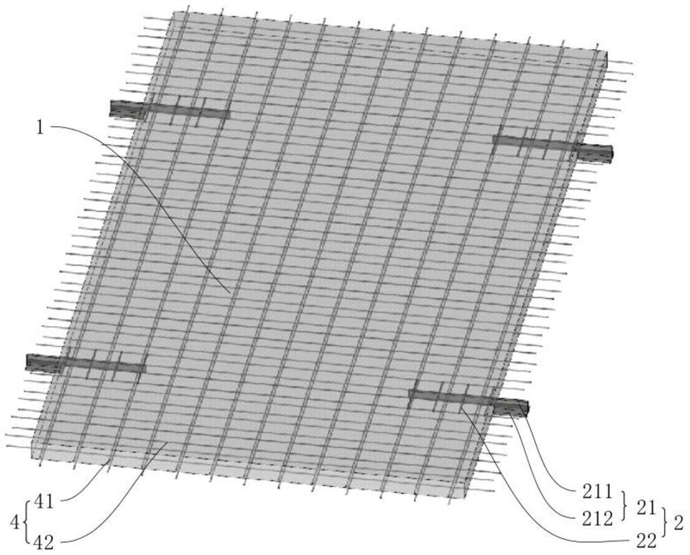
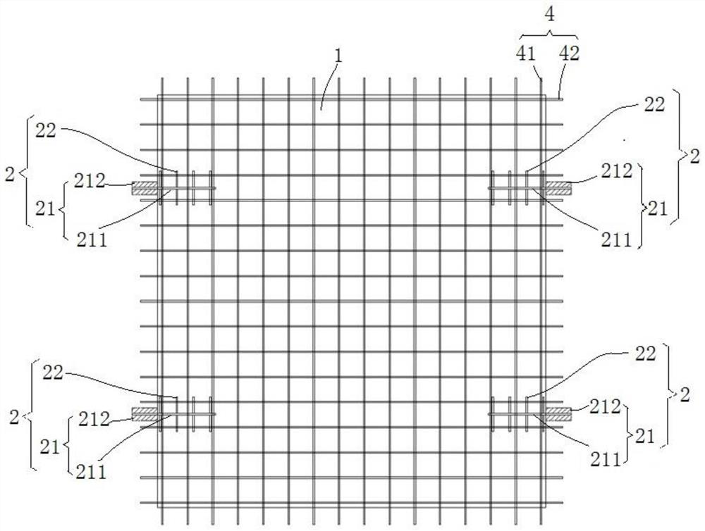
[0048] refer to figure 1 , the support-free precast floor with corbels is a fully precast floor, including a concrete fully precast floor body 1 and several corbels 2, the concrete fully precast floor body 1 here means the concrete floor without corbels 2, and its pouring operation is The construction work of the prefabricated building is completed in advance, and the corbel 2 is buried during the pouring operation, and the corbel 2 is prefabricated before the pouring construction operation of the fully prefabricated concrete floor slab body 1 . Both the corbel 2 and the prefabricated floor slab are prepared using standardized modular operations, which greatly reduces the amount of wet work and formwork work on site.
[0049] see figure 2 , in the span direction of concrete full prefabricated floor slab body 1 ( figure 1 Two sets of corbels 2 are set on the two side walls, each group contains two corbels 2, and each group can contain more than three corbels 2 based on actua...
Embodiment 2
[0065] refer to Figure 7 The difference between this embodiment and Embodiment 1 is that the bottom surface of the vertical steel plate 211 extends downwards from a section of the concrete prefabricated floor body 1, and the upper surface of the horizontal steel plate 212 is higher than the lower surface of the vertical steel plate 211. surface. The shear member 22 is screwed to the vertical steel plate 211 through the through hole. The two side walls of the fully prefabricated concrete floor slab body 1 abut against the side walls of the structural beams or the wall body 3, so that the airtightness is better, and the cement leakage is prevented when pouring the cement. The shear member 22 can adopt a rectangular column. Correspondingly, rectangular through holes are processed on the vertical steel plate 211. This solution can prevent the shear member 22 from rotating relative to the vertical steel plate 211 during the pouring of cement, and the combination between the rect...
Embodiment 3
[0068] refer to Figure 9 , The difference between this embodiment and Embodiment 1 is that the angle between the shear member 22 and the vertical steel plate is 60°.
[0069] The shearing member 22 is welded to one side of the vertical steel plate 211 , and the shearing member 22 gradually inclines horizontally toward the direction of the horizontal steel plate 212 away from the vertical steel plate 211 . The shear member 22 is arranged obliquely, that is, the direction in which the shear member 22 separates from the vertical steel plate 211 is at an acute angle greater than 45°. The shear member 22 is symmetrical on both sides of the vertical steel plate 211. The side bears the same force to avoid uneven force from affecting the shear performance. The number of shear members 22 is reasonably set according to needs, and the cost is saved while fixing the vertical steel plate 211 . The structure enclosed by any adjacent shear members 22 and the vertical steel plates 211 betw...
PUM
 Abstract
Description
Claims
Application Information
 - Generate Ideas
- Intellectual Property
- Life Sciences
- Materials
- Tech Scout
- Unparalleled Data Quality
- Higher Quality Content
- 60% Fewer Hallucinations
Browse by: Latest US Patents, China's latest patents, Technical Efficacy Thesaurus, Application Domain, Technology Topic, Popular Technical Reports.
© 2025 PatSnap. All rights reserved.Legal|Privacy policy|Modern Slavery Act Transparency Statement|Sitemap|About US| Contact US: help@patsnap.com


