
Sludge purification treatment device for water area cleaning

A technology for purification and sludge treatment, applied in the fields of sludge treatment, water/sludge/sewage treatment, dehydration/drying/concentrated sludge treatment, etc. scope and other issues, to achieve the effect of high degree of automation and saving time in salvage

Inactive Publication Date: 2021-06-25
TAIZHOU UNIV
View PDF4 Cites 2 Cited by
  • Summary
  • Abstract
  • Description
  • Claims
  • Application Information

AI Technical Summary

Problems solved by technology

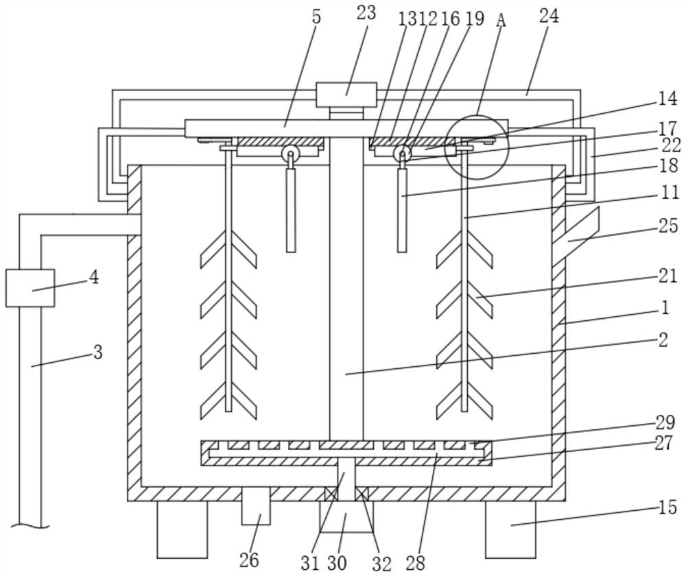
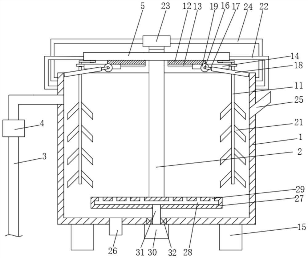
[0003] The object of the present invention is to provide a kind of sludge purification treatment device for water area cleaning, equipped with the simultaneous rotation around the second rotating shaft through the stirring plate, and at this time, the second rotating shaft rotates around the first rotating shaft, thereby increasing the range of stirring and making the stirring It is more uniform and sufficient, and the purification speed is accelerated. Through the reciprocating rotation of the push plate, the floating objects can be continuously pushed out, which saves the time of manual salvage. The effect of high degree of automation solves the problem of the slow speed of sludge treatment in the prior art , the degree of automation is low, the purification quality is not ideal, and it cannot meet the actual needs of people

Method used


Image

  • Sludge purification treatment device for water area cleaning
  • Sludge purification treatment device for water area cleaning
  • Sludge purification treatment device for water area cleaning

Examples


Embodiment Construction

[0025] The following will clearly and completely describe the technical solutions in the embodiments of the present invention with reference to the accompanying drawings in the embodiments of the present invention. Obviously, the described embodiments are only some, not all, embodiments of the present invention. Based on the embodiments of the present invention, all other embodiments obtained by persons of ordinary skill in the art without making creative efforts belong to the protection scope of the present invention.

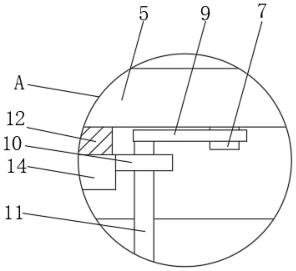
[0026] see Figure 1 to Figure 7 , the present invention provides a technical solution: a sludge purification treatment device for water area cleaning, including a box body 1 and a rotating shaft 1 2, and also includes a rotating shaft 2 7 and a blower 30, and the side wall of the box body 1 is fixedly communicated with a transmission A mud pipe 3, a mud pump 4 is fixedly installed on the mud delivery pipe 3, a mud discharge pipe 26 is fixedly connected to the...


PUM


Abstract

The invention discloses a sludge purification treatment device for water area cleaning, and relates to the technical field of sludge cleaning, the sludge purification treatment device comprises a rotating shaft II and an air blower, a driving mechanism is arranged on a box body, the end parts of two fixed rods I are fixedly connected with an inner gear ring I, the lower end of a rotating shaft I is fixedly connected with an aeration plate, and the air blower is fixedly mounted on the lower surface of the box body. The output end of the air blower is fixedly communicated with a ventilation pipe, the rotating shaft I is provided with a stirring mechanism, a stirring plate rotates around the rotating shaft II and rotates at the same time, and at the moment, the rotating shaft II rotates around the rotating shaft I, so that the stirring range is enlarged, stirring is more uniform and sufficient, and the purification speed is increased; through the reciprocating rotation of a push plate, the floating objects can be continuously pushed out, the manual salvage time is saved, the automation degree is high, and the problems that in the prior art, the sludge treatment speed is low, the automation degree is low, the purification quality is not ideal, and actual needs of people cannot be met are solved.

Description

technical field [0001] The invention relates to the technical field of sludge cleaning, in particular to a sludge purification treatment device for water area cleaning. Background technique [0002] With the continuous development of society, a large amount of residential garbage and industrial waste are discharged into lakes and rivers, resulting in turbidity and discoloration of the water body, and an increase in silt. Sludge environment causes pollution, and it needs to be purified regularly. The speed of sludge treatment in the prior art is slow, the degree of automation is low, and the purification quality is not ideal, which cannot meet the actual needs of the people. Contents of the invention [0003] The object of the present invention is to provide a kind of sludge purification treatment device for water area cleaning, equipped with the simultaneous rotation around the second rotating shaft through the stirring plate, and at this time, the second rotating shaft ro...

Claims


Application Information

Patent Timeline
IPC IPC(8): C02F11/00C02F11/14C02F11/06
CPCC02F11/00C02F11/14C02F11/06C02F2103/007
Inventor 吴娟
Owner TAIZHOU UNIV
Learn More