Axle box built-in bogie based on novel motor suspension structure and flexible interconnection framework

A flexible interconnection and bogie technology, which is applied to the transmission device, bogie, axle box and other directions driven by electric motors, can solve the problems of increasing the structural size and turning radius of the bogie, occupying space, and being unable to maintain, etc., to achieve convenience The effect of independent replacement and maintenance, reduction of occupation time, and improvement of turnover efficiency

Pending Publication Date: 2021-06-25
CRRC CHANGCHUN RAILWAY VEHICLES CO LTD
View PDF2 Cites 0 Cited by
  • Summary
  • Abstract
  • Description
  • Claims
  • Application Information

AI Technical Summary

Problems solved by technology

However, the layout position of the motor hanger t and the gear box hanger u of this installation method that relies on the integral beam body g or the well-shaped beam body h and is completely rigidly connected with the motor hanger t and the gear box hanger u And welding manufacturing process not only puts forward higher requirements on the structural strength and symmetry accuracy of the beam body, but also occupies most of the space inside the conventional frame, resulting in the lack of sufficient axle box layout space inside the existing bogie. As a result, the typical primary suspension device can only be arranged at the two ends of the axle, which not only increases the risk of damage to the axle box, but also increases the overall structural size and turning radius of the bogie, which is not conducive to the improvement of its minimum curve passing capacity. And because the lifting lugs of the casing of the traction motor r are non-removable rigid structures, it interferes with the frame and the gearbox structure and blocks each other, so that the traction motor r cannot be removed from the bottom of the car body directly through the maintenance ditch, but must be used on a truck Only by separating the compartment above the frame from the frame can the traction motor r be withdrawn from the frame, which greatly increases the difficulty of motor maintenance and replacement
At the same time, the rigid connection of the motor hanger t and the gearbox hanger u also leads to the lack of sufficient vibration reduction protection system for the traction motor r and the gearbox s, which in turn makes the auxiliary structures such as the anti-snake shock absorber and the anti-rolling torsion bar n Installation becomes an indispensable and necessary supplement
[0007] In addition, different train design speed requirements or different side beam structures will also have a great impact on the layout space and structural form of the primary suspension device, motor and gearbox, often resulting in the layout of the old primary suspension device. The scheme cannot meet the requirements of the installation location and vibration reduction index, so the old reference scheme must be overthrown, and a design improvement with a new concept must be made
[0008] like Figure 4 to Figure 6 As shown, the existing large gear s-2 installed inside the shell s-1 of the snap-fit ​​and spliced ​​gearbox is directly press-fitted with the bearing outer ring s-3-2 on the large gear bearing s-3 to form a coaxial fixed connection Interference fit, the gear box installation shaft section d-1 on the axle d is directly press-fitted with the large gear bearing inner ring s-3-1 on the large gear bearing s-3 to form a coaxial fixed interference fit, the process The coaxial fixed connection form of the interference fit makes the gearbox installation shaft section d-1, the gearbox bearing s-3 and the large gear s-2 become an inseparable whole, and, due to the snap-fit ​​spliced ​​gearbox shell s- 1 has low structural strength, and it cannot be directly used as the focus point of the withdrawal baffle on the wheel shaft withdrawal press. Moreover, the bearing inner ring of the existing large gear bearing s-3 is too narrow, resulting in that even if the wheel shaft withdrawal pressure The on-board unloading baffle is refitted into a multi-jaw chuck and inserted into the gear box through the axle through hole on the axial side wall of the gear box. However, due to the lack of sufficient radial force points, it is still impossible to reliably clamp the large The inner ring s-3-1 of the gear bearing implements the radial withdrawal blocking force, so that the withdrawal of the axle cannot be directly implemented, and then when the subsequent maintenance of the axle d or the large gear s-2 must be buckled and spliced The gearbox casing s-1 is the first to release the original splicing and fastening state, and the axle d, the large gear s-2 and the large gear bearing s-3 that are coaxially fixed with it are removed from the frame as a whole. Then transfer to the axle unloading press to complete the unloading and replacement operation
The process of this method is cumbersome, time-consuming and labor-intensive, and it is impossible to remove and replace the axle d independently without removing the large gear s-2 from the snap-fit ​​spliced ​​gearbox casing s-1, and it is also impossible to maintain the buckle. Under the premise that the shell s-1 of the spliced ​​gearbox is in the fastened state, pull out the axle d separately and directly repair the large gear s-2 in the shell s-1 of the gearbox from the hole left after the axle d is removed. and lubrication maintenance

Method used


Image

  • Axle box built-in bogie based on novel motor suspension structure and flexible interconnection framework
  • Axle box built-in bogie based on novel motor suspension structure and flexible interconnection framework
  • Axle box built-in bogie based on novel motor suspension structure and flexible interconnection framework

Examples


Embodiment Construction

[0074] The present invention will be further described in detail below with reference to the accompanying drawings.

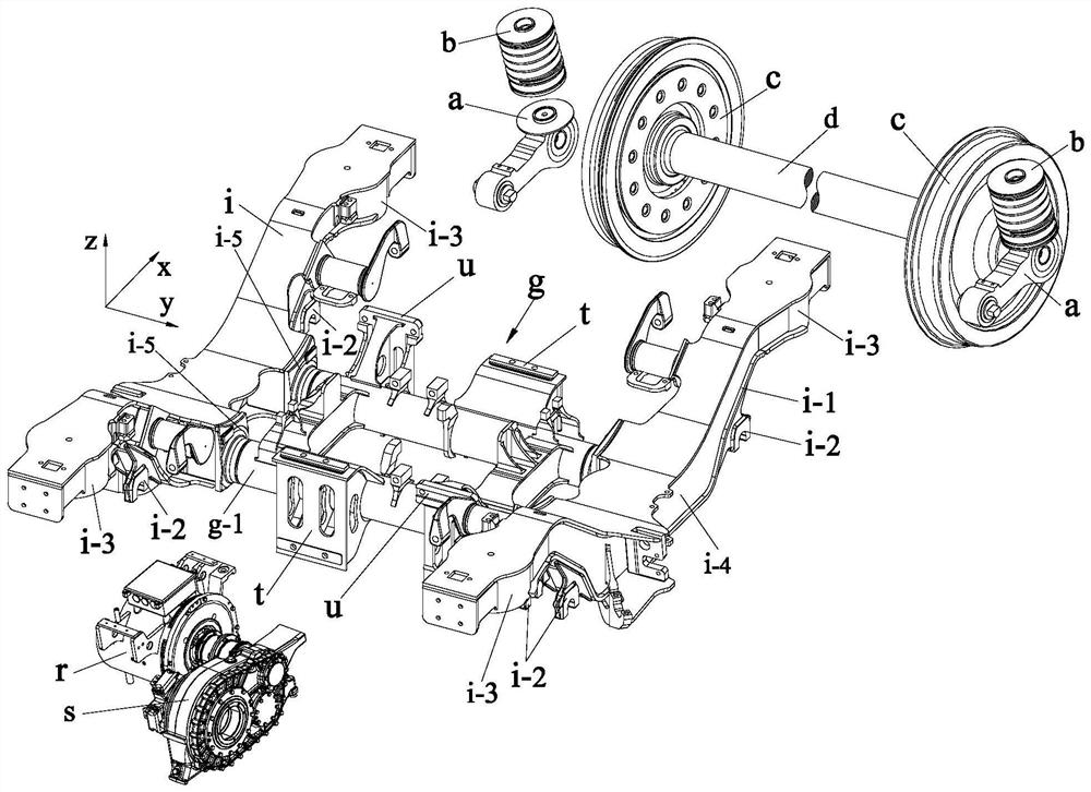
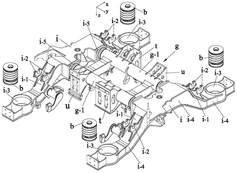
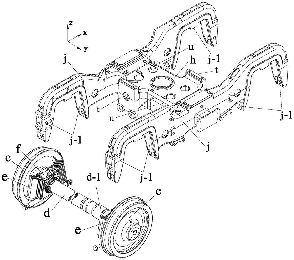
[0075] Such as Figure 7 to 26 As shown, the present invention has an axle box built-in steering frame based on a new motor suspension structure and a flexible interconnect frame comprising a wheel pair of wheel and axle, a cross-sectional flexible interconnect frame, four annular damping shafts Box, easy retractable gearbox and side beam single-point hanging motor;

[0076] The cross sectional flexible interconnect structure includes two cross-sectional integrated structures that are rotationally symmetrical, each of which includes integrated integrated side beams 1-1 and integrated beams 1-2; integrated The type side beam 1-1 includes two bird wing connecting portions and the lateral beams of the side beams from the lower position and two symmetrical solids in the middle end of the side beams 1-1-1. Section 1-1-2, the bird wing side beam cantilever section 1-1-2 i...


PUM


Abstract

The invention discloses an axle box built-in bogie based on a novel motor suspension structure and a flexible interconnection framework, and belongs to the field of railway vehicle power bogie devices. The axle box built-in bogie comprises a wheel set device composed of wheels and axles, a transverse and longitudinal integrated flexible interconnection framework, four annular vibration reduction axle boxes, an easy-to-withdraw axle type gearbox and a side beam single-point suspension type motor. The damping requirement for the whole framework is greatly reduced, and the effects of reducing the number of parts and the failure rate, releasing the layout space and maintenance operation allowance of a motor and a gearbox, simplifying the framework size and simplifying the manufacturing process are achieved; according to the invention, after fastening bolts of four motor flexible suspension rubber nodes and fastening bolts of side beam end motor suspension rubber nodes are respectively dismounted, the side beam single-point suspension type motor can be directly and independently dismounted from the lower part of a vehicle body through a maintenance trench.

Description

Technical field [0001] The invention belongs to the field of power bogie devices for rail vehicles, and specifically relates to an axle box built-in bogie based on a new motor suspension structure and a flexible interconnection frame. Background technique [0002] When designing a rail train bogie, it is not only necessary to comprehensively consider comprehensive factors such as the structural strength and flexibility of the frame as the main load-bearing body, the effect of various auxiliary damping components such as anti-snaking dampers, and the installation method of the braking mechanism, but also In response to the needs of different vehicle models, the suspension method of the power bogie motor, the placement of the axle box on the axle, the motor and its There are many factors such as the layout space of the gear box, the structural form and layout space of the primary and secondary suspension devices. Various design solutions based on the above core ideas have bec...

Claims


Application Information

Patent Timeline
IPC IPC(8): B61F5/52B61F5/50B61C9/50B61F15/20B61F5/30
CPCB61F5/52B61F5/50B61C9/50B61F15/20B61F5/305
Inventor 张文康韩俊臣丁富昌秦强
Owner CRRC CHANGCHUN RAILWAY VEHICLES CO LTD
Why Eureka
Try Eureka