
Implant conveying device and inner tube assembly and catheter thereof

A technology of implants and inner tubes, which is applied in the field of catheters, implant delivery devices and inner tube components, can solve problems such as ignoring the role of the fixed head, invagination, and implant distortion, so as to ensure valve leaflet fatigue performance, The effect of reducing damage and protecting valve leaflets

Pending Publication Date: 2021-06-25
SHANGHAI MICROPORT CARDIOFLOW MEDTECH CO LTD
View PDF0 Cites 1 Cited by
  • Summary
  • Abstract
  • Description
  • Claims
  • Application Information

AI Technical Summary

Problems solved by technology

During the entire loading process, especially for circumferentially asymmetrical stents, the implant is prone to inclination and damage due to poor uniformity of force. will aggravate the problem of poor uniformity of force on the bracket
At the same time, during the release process, the implant may also be twisted, invaginated, damaged or even unable to be used normally.
In addition, when one end surface of the leaflet of the self-expanding stent is equal to or close to the end surface of the stent, the stent will squeeze the leaflet during loading and release, causing damage to the leaflet and affecting its use.
In the prior art, generally by improving the conveyor catheter, implant or loading tool, the scheme is complicated, the cycle is long, and the cost is high; the role of the fixed head in it is ignored

Method used


Image

  • Implant conveying device and inner tube assembly and catheter thereof
  • Implant conveying device and inner tube assembly and catheter thereof
  • Implant conveying device and inner tube assembly and catheter thereof

Examples


Embodiment Construction

[0039] The present invention will be further described below in conjunction with the accompanying drawings and embodiments.

[0040] In the following description, numerous specific details are set forth in order to provide a thorough understanding of the present invention. It will be apparent, however, to one of ordinary skill in the art that the present invention may be practiced without these specific details. Therefore, the specific details set forth are merely exemplary, and specific details may be varied in the spirit and scope of the invention and still be considered to be within the spirit and scope of the invention.

[0041]It should be noted that when an element is referred to as being “fixed” to another element, it may be directly fixed on the other element or there may be an intermediate element through which one element is indirectly fixed to another element. When an element is referred to as being "connected" to another element, it can be directly connected to th...


PUM


Abstract

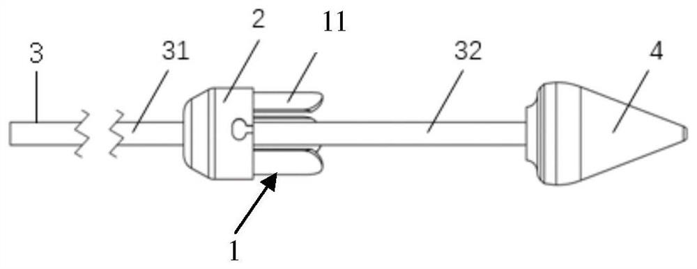
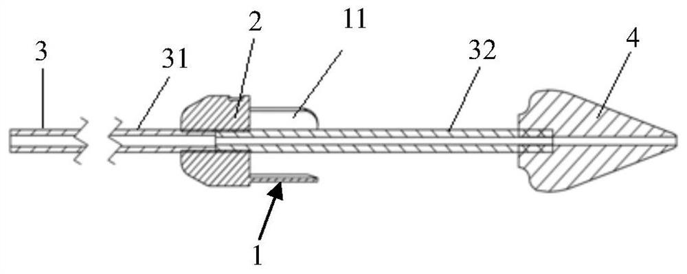
The invention discloses an implant conveying device and an inner tube assembly and a catheter thereof, the inner tube assembly comprises an implant protection part, an inner tube and a fixing head connected with the inner tube, and the implant protection part is connected with the inner tube or / and the fixing head. The implant protection part is used for being in contact with an implant so as to support the implant; and a protection body is in a circular ring sheet shape or an arc sheet shape. According to the implant conveying device provided by the invention, the implant protection part is arranged, so that a non-anchoring rod with relatively weak circumferential supporting force of a valve stent can be supported, and inclination and damage of the valve stent in a loading process and distortion and inward sinking of the valve stent in a releasing process are avoided.

Description

technical field [0001] The invention relates to an implant delivery system, in particular to an implant delivery device and its inner tube assembly and catheter. Background technique [0002] The implant, such as a self-expanding stent, needs to have a specific structure during the loading and releasing process, and be fixed with the corresponding structure of the conveyor by means of shape fit or pull wire, which can be fixed at one end or at both ends. In this way, the stable pressing and releasing of the implant by the conveyor is realized. This specific structure on the implant is called an ear, and the corresponding structure on the delivery system is called a fixation head. Hanging ears can appear at any node on the bracket. If it is a single-layer bracket, the hanging ears are usually set on one end of the bracket; if it is a double-layer bracket, the hanging ears are usually set on one end of the inner or outer bracket. However, after the double-layer bracket is cr...

Claims


Application Information

Patent Timeline
Patent Type & Authority Applications(China)
IPC IPC(8): A61F2/95A61F2/24
CPCA61F2/95A61F2/24A61F2002/9528A61F2/2436A61F2/9522A61F2002/9534A61F2/2418
Inventor 吴旭闻梅杰石若璘邱尧桂宝珠陈国明李雨
Owner SHANGHAI MICROPORT CARDIOFLOW MEDTECH CO LTD
Learn More