
High-speed multi-directional line confocal digital holographic three-dimensional microscopic imaging method and device

A digital holographic and microscopic imaging technology, which is applied in the direction of instruments, can solve the problem that the two-dimensional lateral resolution isotropy cannot be achieved, and achieve the effect of high-speed multi-directional line confocal digital holographic microscopic imaging

Active Publication Date: 2022-03-11
ZHEJIANG UNIVERSITY OF SCIENCE AND TECHNOLOGY
View PDF0 Cites 0 Cited by
  • Summary
  • Abstract
  • Description
  • Claims
  • Application Information

AI Technical Summary

Problems solved by technology

However, the prior technologies can only achieve line confocal in one-dimensional direction, and cannot achieve isotropy in two-dimensional lateral resolution.

Method used


Image

  • High-speed multi-directional line confocal digital holographic three-dimensional microscopic imaging method and device
  • High-speed multi-directional line confocal digital holographic three-dimensional microscopic imaging method and device
  • High-speed multi-directional line confocal digital holographic three-dimensional microscopic imaging method and device

Examples


Embodiment 1

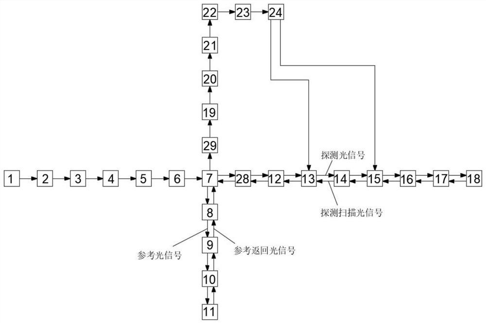
[0043] Embodiment 1: After the optical signal generated by the single-frequency single-mode continuous laser is polarized, beam expanded and focused by a cylindrical lens, it is divided into a reference optical signal and a detection optical signal by a polarization beam splitting prism; the reference optical signal is passed through the first The lens group is relayed to the total reflection mirror and receives the reference return light signal; the detection light signal is relayed to the sample platform through the second lens group and receives the detection scanning light signal, wherein the second lens group is equipped with a one-dimensional fast scanner and line The fast scanning direction switching unit uses a one-dimensional fast scanner to realize line scanning of a certain direction of the sample platform, and uses the fast line scanning direction switching unit to realize fast switching of multiple scanning directions; the reference return optical signal and the det...

Embodiment 2

[0045] Embodiment 2: On the basis of embodiment 1, specifically, adopt 633nm single-frequency single-mode continuous laser, laser line width 10kHz, output power is 20mW, the optical signal that single-frequency single-mode continuous laser produces at first through polarizing, ensures The polarization extinction ratio is greater than 25dB. The beam is expanded by a 10× beam expander, and then passes through a half-wave plate and a rectangular aperture. The rectangular aperture is located on the front focal plane of the cylindrical lens. The focal length of the cylindrical lens is 50mm, and the length of the rectangular aperture is 5mm. ; After the optical signal passes through the cylindrical lens, a focused line beam is generated on the rear focal plane and enters the 1×2 polarizing beam splitting prism, which is divided into a reference optical signal and a detection optical signal by the 1×2 polarizing beam splitting prism. The beam ratio is controlled by a half-wave plate, ...


PUM


Abstract

The invention discloses a high-speed multi-directional line confocal digital holographic three-dimensional microscopic imaging method and device. The optical signal is divided into a reference optical signal and a detection optical signal after being polarized, beam expanded and focused; the reference optical signal is relayed to The total reflection mirror receives the reference return light signal; the detection light signal is relayed to the sample platform and receives the detection scanning light signal; the reference return light signal and the detection scanning light signal are combined to filter out stray light, and then relayed to the high-speed linear array The photosensitive surface of the camera obtains multi-frame one-dimensional line confocal interferograms; multi-frame one-dimensional line confocal interferograms are collected and superimposed to generate reconstruction interference fields in multiple scanning directions, and then processed to realize the expansion of the object optical spectrum of the sample platform , and then process the expanded object light spectrum to reconstruct the three-dimensional phase distribution of the object light wave field. The invention can effectively realize high-speed multi-directional line confocal digital holographic microscopic imaging, and has the advantage of high resolution.

Description

technical field [0001] The invention relates to the technical field of three-dimensional microscopic imaging, in particular to a high-speed multi-directional line confocal digital holographic three-dimensional microscopic imaging method and device. Background technique [0002] Digital holographic three-dimensional imaging technology follows the theory of optical holographic recording, uses photodetectors instead of ordinary holographic recording media to record interferograms, replaces optical diffraction with computer numerical calculations to reproduce the recorded object light wave field, and obtains the amplitude information and Phase information, the entire recording and reproduction process is digitized, is a non-contact, non-destructive and high-resolution 3D imaging technology for measuring phase changes in media, and is expected to become a powerful tool for research in the field of 3D micro-nano imaging. [0003] Spatial resolution is an important index for evalua...

Claims


Application Information

Patent Timeline
Patent Type & Authority Patents(China)
IPC IPC(8): G03H1/00G03H1/08G03H1/04
CPCG03H1/0005G03H1/0866G03H1/0808G03H1/0443G03H2001/005G03H2001/0038G03H2001/0445
Inventor 职亚楠邹瑜徐弼军田克汉
Owner ZHEJIANG UNIVERSITY OF SCIENCE AND TECHNOLOGY
Learn More