Long-distance multi-parameter synchronous detection system for bridge
A synchronous detection, multi-parameter technology, applied in the direction of elasticity test, machine/structural component test, measurement device, etc., can solve the problem that the detection method cannot collect bridge parameters in time, achieve accurate judgment results, improve accuracy, Exclude abnormal effects
- Summary
- Abstract
- Description
- Claims
- Application Information
AI Technical Summary
Problems solved by technology
Method used
Image
Examples
Embodiment 1
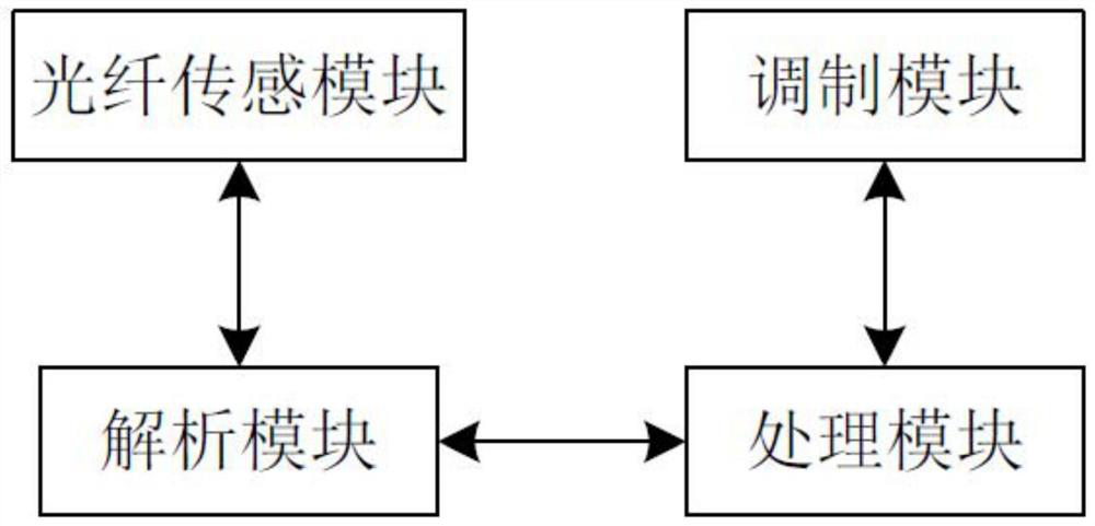
[0025] Long-distance multi-parameter simultaneous detection system for bridges, such as figure 1 As shown: it includes an analysis module, a modulation module, and an optical fiber sensing module. The analysis module sends the optical signal to the modulation module. The analysis module can use an existing optical fiber decoder. A plurality of frequencies arranged in the second order are modulated into a first detection signal and a second detection signal, and the modulation module sends the first detection signal and the second detection signal to the optical fiber sensing module respectively, and the optical fiber sensing module is along the length of the bridge Direction laying, the optical fiber sensing module is located inside the bridge or on the outer wall of the bridge. The optical fiber sensing module transmits the first detection signal and the second detection signal respectively and simultaneously senses the change information of the bridge. The change information ...
Embodiment 2
[0039] The difference from Embodiment 1 is that the processing module sends abnormal point information to the analyzing module when the optical fiber sensing module is located in the bridge.
[0040] When the optical fiber sensing module is located in the bridge, it is impossible to visually see the corresponding abnormal situation, and the abnormal point information is sent to the analysis module, so as to know the abnormal situation inside the bridge in time.
Embodiment 3
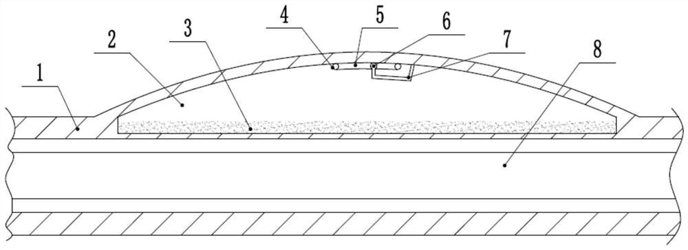
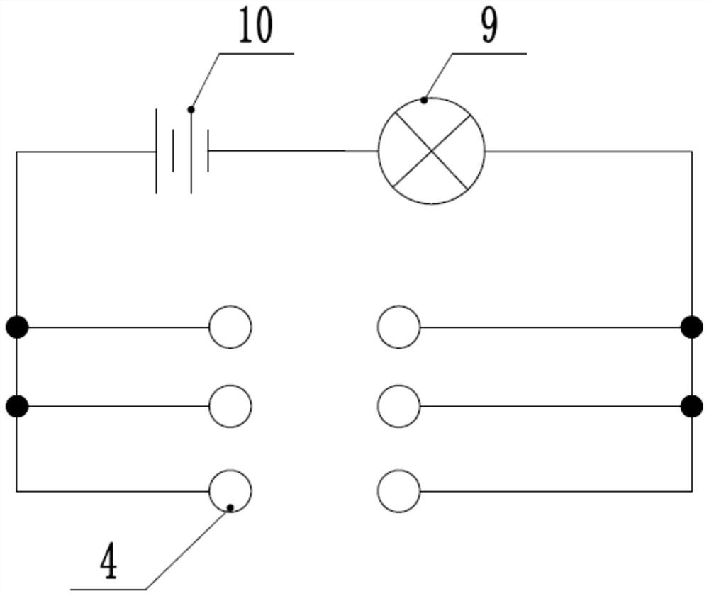
[0042] The difference with Embodiment 1 is that, if figure 2 and image 3 , the reference signs in the figure are: elastic tube 1, cavity 2, metal powder 3, conductive terminal 4, groove 5, friction head 6, friction rod 7, optical fiber sensing module 8, indicator 9, power supply 10.
[0043] It also includes a transition piece located at the bridge joint gap, the transition piece includes an elastic tube 1 sleeved outside the optical fiber sensing module 8, the two ends of the elastic tube 1 are fixedly connected to the bridges at both ends of the joint point gap, and the elastic tube 1 The outer tube wall facing upward is arc-shaped, and the elastic tube 1 is provided with a plurality of cavities 2 on the upward tube wall, the cavities 2 are filled with metal powder 3, and the top wall of the cavity 2 is bonded with friction The friction strip is provided with a groove 5, the inner wall of the groove 5 is arc-shaped, the two ends of the friction strip are bonded with condu...
PUM
 Abstract
Description
Claims
Application Information
 - R&D
- Intellectual Property
- Life Sciences
- Materials
- Tech Scout
- Unparalleled Data Quality
- Higher Quality Content
- 60% Fewer Hallucinations
Browse by: Latest US Patents, China's latest patents, Technical Efficacy Thesaurus, Application Domain, Technology Topic, Popular Technical Reports.
© 2025 PatSnap. All rights reserved.Legal|Privacy policy|Modern Slavery Act Transparency Statement|Sitemap|About US| Contact US: help@patsnap.com


