
Liquid switch valve structure and using method thereof

A technology of liquid switching and switching valves, which is applied in the direction of valve devices, valve details, valve operation/release devices, etc., which can solve the inconvenient automatic opening of liquid switching valves for pressure relief, inconvenient sealing installation of liquid switching valves, and inconvenient liquid Problems such as filtering and processing to achieve the effect of avoiding random offset, convenient limit, and convenient regulation

Inactive Publication Date: 2021-06-22
尹红绕
View PDF1 Cites 2 Cited by
  • Summary
  • Abstract
  • Description
  • Claims
  • Application Information

AI Technical Summary

Problems solved by technology

[0009] The object of the present invention is to provide a liquid on-off valve structure and its use method to solve the problem that the existing liquid on-off valve structure proposed in the above background technology is inconvenient to filter the liquid in the pipeline, and the flowing liquid is easy to cause damage to the valve. Corrosion affects the service life. At the same time, there is no pressure relief pipe installed in the liquid pipeline. When the internal pressure of the pipeline is too high, it is inconvenient to automatically open the liquid on-off valve for pressure relief, and it is easy to damage the liquid on-off valve. Sealed installation, prone to liquid leakage, affecting the use of problems

Method used


Image

  • Liquid switch valve structure and using method thereof
  • Liquid switch valve structure and using method thereof
  • Liquid switch valve structure and using method thereof

Examples


Embodiment Construction

[0044] The following will clearly and completely describe the technical solutions in the embodiments of the present invention with reference to the accompanying drawings in the embodiments of the present invention. Obviously, the described embodiments are only some, not all, embodiments of the present invention. Based on the embodiments of the present invention, all other embodiments obtained by persons of ordinary skill in the art without making creative efforts belong to the protection scope of the present invention.

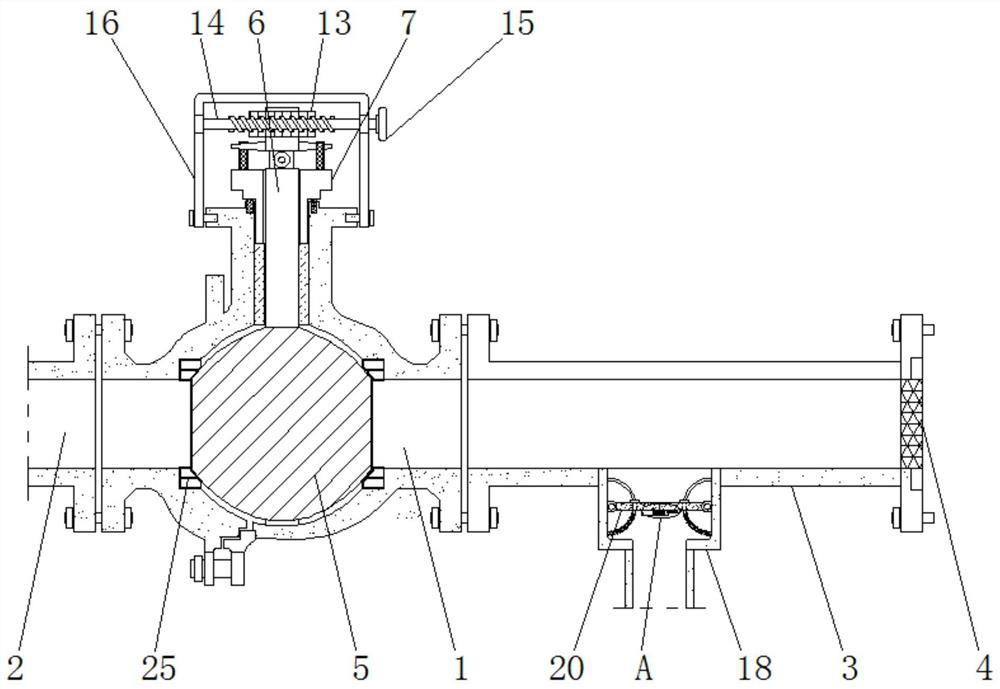
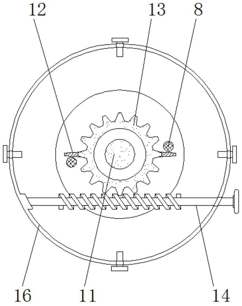
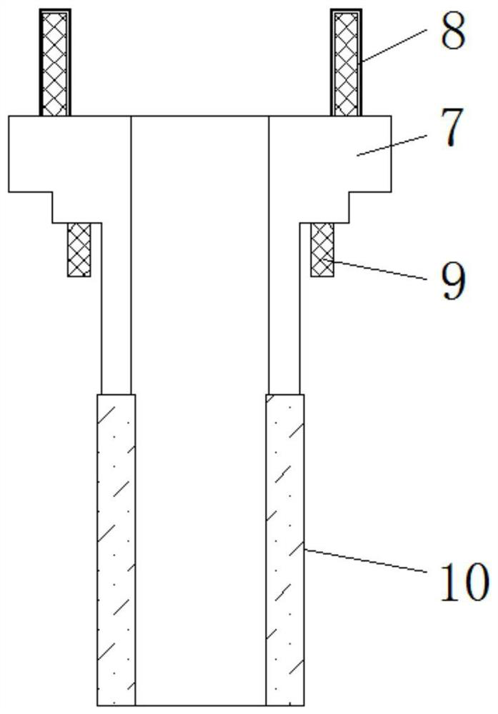
[0045] see Figure 1-9 , the present invention provides a technical solution: a liquid switch valve structure, including a valve body shell 1, a switch valve body 5 and an electric telescopic rod 21, the left and right ends of the valve body shell 1 are respectively connected to each other through flanges and installed with water outlets. The pipe 2 and the water inlet pipe 3, and the right inner wall of the water inlet pipe 3 is fitted with a filter 4 for filte...


PUM


Abstract

The invention discloses a liquid switch valve structure and a using method thereof. The liquid switch valve structure comprises a valve body shell and a switch valve body. The left end and the right end of the valve body shell communicate with a water outlet pipeline and a water inlet pipeline through flanges correspondingly, and meanwhile a filter screen is clamped to the inner wall of the right side of the water inlet pipeline; the switch valve body is rotationally installed in the valve body shell, a rotating rod is fixedly connected to the middle of the switch valve body, and meanwhile a sealing block is tightly installed between the valve body shell and the switch valve body. According to the liquid switch valve structure and the using method thereof, liquid in a pipeline can be conveniently filtered, the flowing liquid is prevented from corroding the valve and affecting the service life, meanwhile, a pressure relief pipeline is installed in the liquid pipeline, when the internal pressure of the pipeline is too large, the liquid switch valve can be conveniently and automatically opened for pressure relief, the liquid switch valve is prevented from being damaged, the liquid switch valve can be conveniently installed in a sealed manner, the situation of liquid leakage is avoided, and use is prevented from being affected.

Description

technical field [0001] The invention relates to the related technical field of liquid on-off valves, in particular to a liquid on-off valve structure and its usage method. Background technique [0002] At present, in the field of construction equipment, shoes and clothing, and other industrial fields, spray glue, water spray, or other liquid media are often used to attach to the surface of the processed object. For different products, the sprayed adhesion area and adhesion medium The thickness and spraying frequency are all different, and liquid medium switching valves are required for control. Since the frequency of liquid spraying is usually high, there are extremely high requirements for the service life of liquid medium switching valves and fatigue test performance. Avoid liquid medium switching Valves are frequently damaged. [0003] Refer to the authorized announcement number CN105972229B, a liquid pipeline cut-off valve structure and use method, which has the advanta...

Claims


Application Information

Patent Timeline
Patent Type & Authority Applications(China)
IPC IPC(8): F16L55/24F16K41/04F16K31/53F16L55/07
CPCF16K31/535F16K41/046F16L55/07F16L55/24
Inventor 尹红绕
Owner 尹红绕
Learn More