Eureka AIR delivers breakthrough ideas for toughest innovation challenges, trusted by R&D personnel around the world.

Heat dissipation air inlet cabin and unmanned aerial vehicle applying same

A technology of air inlet and air inlet channel, which is applied in the cooling system of aircraft parts, power plant, transportation and packaging, etc., which can solve the problems of increased flight resistance, impact on the flight performance and safety of the whole aircraft, unstable flow, etc., and achieve The effect of uniform flow velocity distribution, good air intake efficiency, and stable gas flow velocity

Inactive Publication Date: 2021-06-22
北京北航天宇长鹰无人机科技有限公司
View PDF10 Cites 0 Cited by
  • Summary
  • Abstract
  • Description
  • Claims
  • Application Information

AI Technical Summary

Problems solved by technology

[0004] However, for UAVs with a rear-mounted power system, the flow field at the tail of the main body of the fuselage is very complicated, and it is prone to air separation and unstable flow
At this time, the use of traditional heat dissipation and air intake cabins often leads to increased flight resistance, which affects the flight performance and safety of the entire aircraft

Method used


Image

  • Heat dissipation air inlet cabin and unmanned aerial vehicle applying same
  • Heat dissipation air inlet cabin and unmanned aerial vehicle applying same
  • Heat dissipation air inlet cabin and unmanned aerial vehicle applying same

Examples


Embodiment Construction

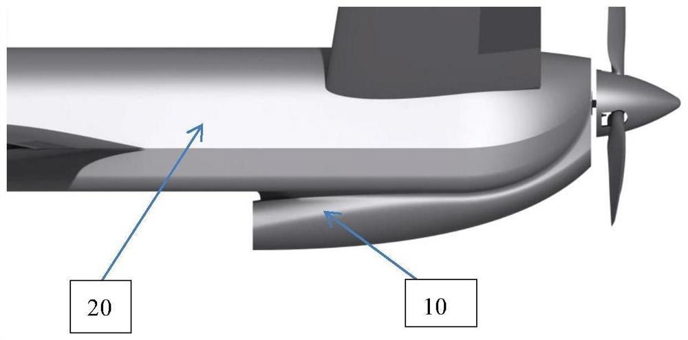
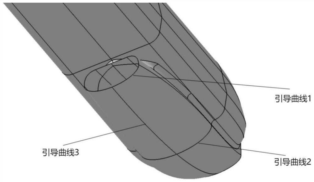
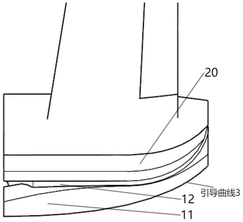
[0043] The invention provides a heat dissipation air intake cabin and an unmanned aerial vehicle using the same. In the heat dissipation air intake cabin, through the unique design of the curved surface of the outer bottom of the cabin outer cover, the shape of the heat dissipation air inlet channel, and the boundary layer shunt mechanism, etc., it can It achieves the purpose of reducing the additional resistance brought by the installation of the heat dissipation air intake cabin, ensuring the stability of the gas flow rate in the heat dissipation air intake channel, and improving the air intake efficiency.

[0044] In order to make the object, technical solution and advantages of the present invention clearer, the present invention will be further described in detail below in combination with specific embodiments and with reference to the accompanying drawings. It should be understood that these embodiments are provided only so that the invention will satisfy legal requiremen...


PUM


Abstract

The invention provides a heat dissipation air inlet cabin and an unmanned aerial vehicle applying the same. According to the heat dissipation air inlet cabin, the bottom face of the outer side of the cabin outer cover extends backwards in a streamline mode, the tail portion of the cabin outer cover is gently retracted upwards, the heat dissipation air inlet channel and the radiator in the cabin outer cover can be completely wrapped, rectification is conducted on the rear portion of the fuselage, and the resistance reduction effect is achieved. In addition, through the unique design of a boundary layer flow dividing mechanism and the like, the purposes of guaranteeing the stable flow speed of gas in the heat dissipation air inlet channel and improving the air inlet efficiency can be achieved.

Description

technical field [0001] The invention relates to the field of aircraft aerodynamic layout, in particular to a heat dissipation air inlet cabin and an unmanned aerial vehicle using the same. Background technique [0002] Unmanned aircraft, referred to as "unmanned aerial vehicle", or "UAV" in English, is an unmanned aircraft that is controlled by radio remote control equipment and its own program control device, or is completely or intermittently operated autonomously by an on-board computer. [0003] Low-speed drones are a category of drones, which have the characteristics of high lift-to-drag ratio, high ceiling, long endurance, and large load capacity. This type of drone mostly adopts a propulsion layout, with the power system arranged at the rear of the fuselage, and the task load arranged at the nose, which is conducive to the balance of the center of gravity and the mounting of weapons. [0004] However, for UAVs with a rear power system, the flow field at the tail of t...

Claims


Application Information

Patent Timeline
Patent Type & Authority Applications(China)
IPC IPC(8): B64C7/00B64D33/08
CPCB64C7/00B64D33/08
Inventor 王晨先王靖欢梁阳
Owner 北京北航天宇长鹰无人机科技有限公司
Why Eureka
Eureka Blog
Learn More