Plasma flue gas desulfurization, denitrification and dust removal integrated device

A desulfurization, denitrification, and plasma technology, applied in gas treatment, separation methods, transportation and packaging, etc., can solve the problems of interrupting the flue gas treatment process, time-consuming and labor-intensive flushing of the dust collector, clogging of the dust collector, etc., so as to ensure the clamping efficiency. , Increase the effect of filtering and dust removal, and increase the effect of cleaning efficiency

Pending Publication Date: 2021-06-22
谭卫成
View PDF13 Cites 1 Cited by
  • Summary
  • Abstract
  • Description
  • Claims
  • Application Information

AI Technical Summary

Problems solved by technology

[0006] In order to make up for the deficiencies of the existing technology and solve the problem in the prior art, the flue gas to be treated enters the rotating dust removal cylinder through the air inlet, and then undergoes plasma oxidation treatment and desulfurization treatment, but the dust removal chamber accumulates a large amount of impurities after filtering for a long time , resulting in the blockage of the dust removal cylinder, which in turn affects the filtration and passing efficiency of the flue gas. It takes time and energy to disassemble and flush the dust removal chamber, and interrupt the treatment process of the flue gas. A plasma flue gas desulfurization, denitrification and dust removal integrated device proposed by the present invention

Method used


Image

  • Plasma flue gas desulfurization, denitrification and dust removal integrated device
  • Plasma flue gas desulfurization, denitrification and dust removal integrated device
  • Plasma flue gas desulfurization, denitrification and dust removal integrated device

Examples


Embodiment approach

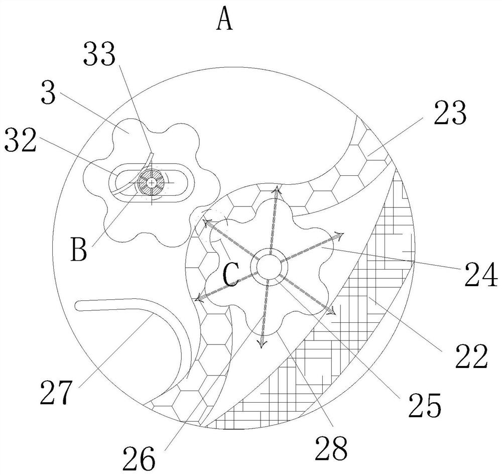
[0032] As an embodiment of the present invention, a group of arc-shaped teeth 28 are evenly distributed on the outer periphery of the driving roller 24, and a driven roller 3 is arranged on the inner periphery of the filter cloth 23 corresponding to the driving roller 24, and the driven roller 3 The outer periphery is provided with an arc-shaped groove matching with the teeth 28; the middle part of the driven roller 3 is fixedly connected with the second rotating shaft 31, and the position corresponding to the second rotating shaft 31 is provided with a chute 32 on the box body 1, and the second rotating shaft 31 It runs through the chute 32 and is slidably connected with the chute 32; the side of the chute 32 away from the driving roller 24 is fixedly connected with an arc-shaped elastic piece 33, and the middle part of the elastic piece 33 resists and presses the second rotating shaft 31; through the teeth 28 Cooperate with the arc-shaped groove of the driven roller 3, so tha...


PUM


Abstract

The invention belongs to the technical field of dust removal equipment, and particularly relates to a plasma flue gas desulfurization, denitrification and dust removal integrated device, which comprises a box body, an air inlet is formed in one side of the box body, an exhaust port is formed in the other side of the box body, and a dust removal unit, a plasma oxidation unit and a desulfurization unit are sequentially arranged in the box body from the air inlet to the exhaust port; the dust removal unit comprises a first rotating shaft and a filter cylinder, the filter cylinder is in a rigid hollow cylinder shape, and the filter cylinder is rotationally connected with the box body through the first rotating shaft; the end, extending out of the box, of the first rotating shaft is driven by a motor, flexible annular filter cloth is arranged in the filter cylinder, a flexible magnetic strip is arranged on the periphery of the filter cloth, and the filter cloth is attached to the inner periphery of the filter cylinder; a flexible falling curtain is fixedly connected in the box body at the top of the filter cylinder through a bracket; the falling curtain is attached to the periphery of the filter cylinder; according to the invention, the flexible filter cloth can be quickly disassembled to replace new filter cloth, so that the cleaning efficiency of the filter cylinder is improved, and the filtering and dust removing effects of flue gas are further improved.

Description

technical field [0001] The invention belongs to the technical field of dust removal equipment, in particular to an integrated device for desulfurization, denitrification and dust removal of plasma flue gas. Background technique [0002] The main purpose of tail gas treatment is to remove toxic and harmful substances and smoke in industrial production exhaust gas, so that it can be discharged up to standard after treatment and reduce air pollution. The basic types of waste gas are divided into: industrial organic waste gas, boiler smoke and dust waste gas, industrial acid and alkali waste gas, industrial production odor and industrial harmful fine particles, etc. [0003] There are also some technical solutions about dust removal equipment in the prior art. For example, a Chinese patent with application number 2015209677120 discloses an integrated equipment for dust removal, desulfurization and denitrification, including a box body, a dust collector, a plasma oxidation device...

Claims


Application Information

Patent Timeline
Patent Type & Authority Applications(China)
IPC IPC(8): B01D46/02B01D46/00B01D53/78B01D53/50B01D53/32B01D53/56
CPCB01D46/02B01D53/502B01D53/32B01D53/56B01D2258/0283B01D2251/404B01D2251/604B01D2259/818B01D46/72
Inventor 谭卫成
Owner 谭卫成
Why Eureka
Try Eureka