Dust removing device with function of manually shaking off dust for environmental protection

A dust removal device, an environmentally friendly technology, applied in transportation and packaging, separation of dispersed particles, chemical instruments and methods, etc., can solve the problems of unfavorable surrounding environmental protection, slow dust removal effect, limited filter area, etc., and achieve enhanced filtration and dust removal effect of equipment , Improve the scope of action, improve the effect of dust removal ability

Inactive Publication Date: 2018-05-29
王涛
View PDF5 Cites 0 Cited by
  • Summary
  • Abstract
  • Description
  • Claims
  • Application Information

AI Technical Summary

Problems solved by technology

The existing dust removal equipment often sends air into the equipment through the induced draft fan, and then directly filters the air entering the pipeline. In this way, due to the limited area of ​​the filter screen, a large amount of dust and other impurities are attached to the surface of the filter screen after a large amount of dust removal work. Clogging the filter mesh results in a decrease in the dust removal effect, which is not conducive to dust removal. At the same time, due to the small filter area, the dust removal effect is slow, which is not conducive to the protection of the surrounding environment.

Method used


Image

  • Dust removing device with function of manually shaking off dust for environmental protection
  • Dust removing device with function of manually shaking off dust for environmental protection
  • Dust removing device with function of manually shaking off dust for environmental protection

Examples


Embodiment Construction

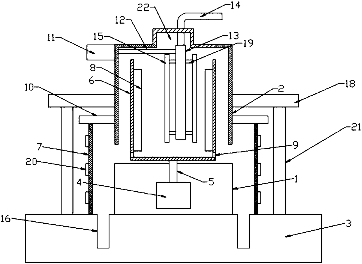
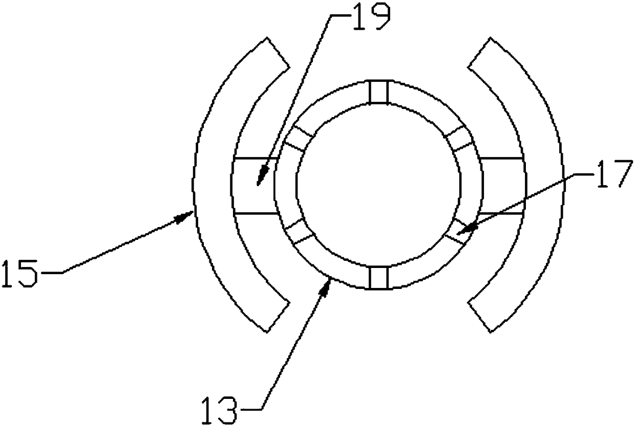
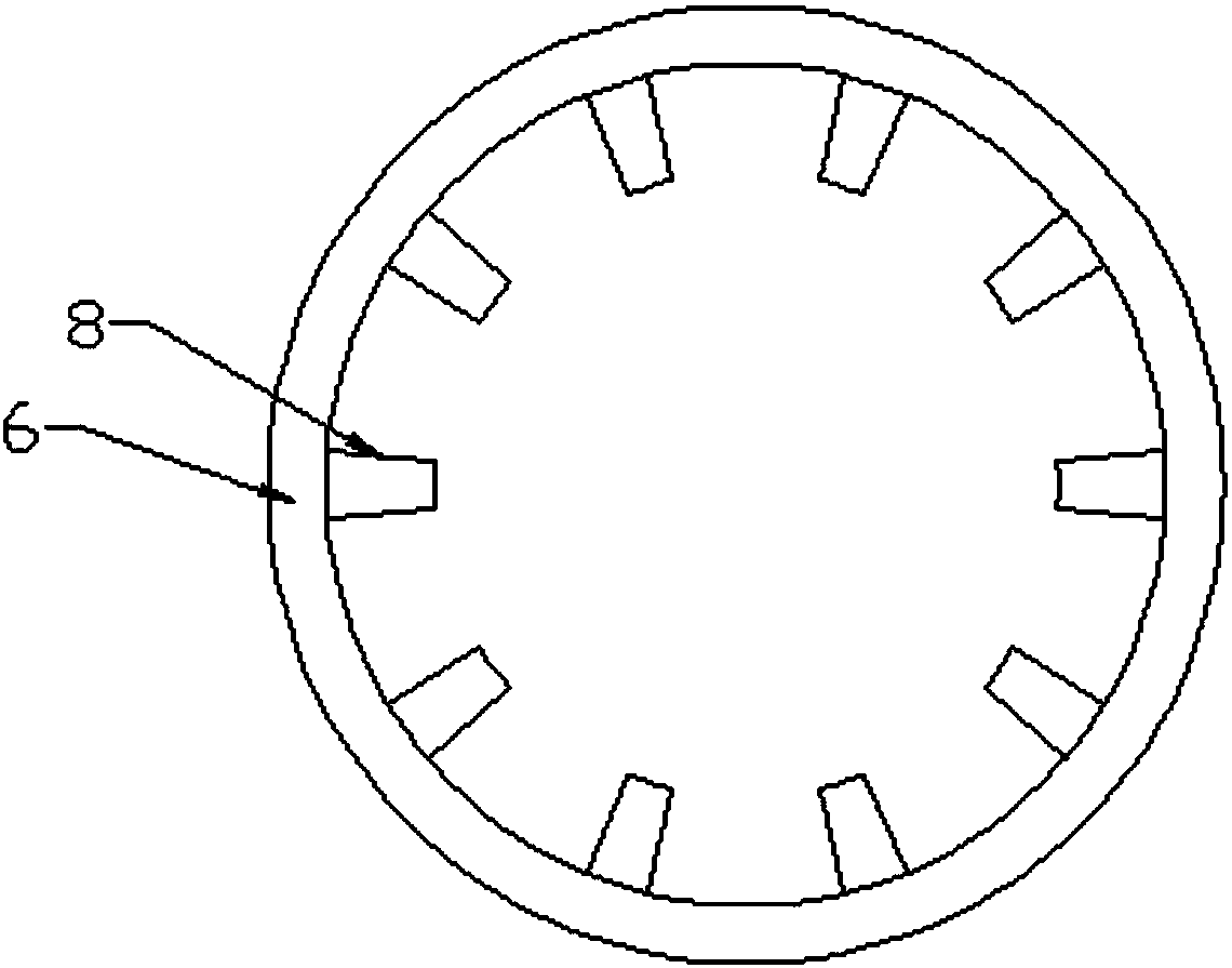
[0018] Please refer to the figure, in the embodiment of the present invention, a dust removal device for environmental protection that manually shakes off dust includes a base 1, a casing 2, a bottom plate 3, a motor 4 and a cylinder 11; the base 1 is fixedly installed with a vertical upward The motor 4 is fixedly connected with the rotating shaft 5 protruding from the base 1 on the output shaft of the motor 4, the upper end of the rotating shaft 5 is fixedly connected with the inner cylinder 6, and is located on the central axis of the inner cylinder 6, at the bottom of the inner cylinder 6 There are several air outlet holes 9 on the side wall, and the inner cylinder 6 rotates to blow out the internal air from the air outlet holes 9, and the air is evenly blown out to the surrounding; on the inner wall of the inner cylinder 6, there are several Stirring blades 8 are used to quickly diffuse the incoming air into the inner cylinder 6 , and stirring blades 8 are also arranged on ...


PUM

PropertyMeasurementUnit
Lengthaaaaaaaaaa

Abstract

The invention discloses a dust removing device with a function of manually shaking off dust for environmental protection. The dust removing device comprises a base, a shell, a bottom plate, a motor and a cylinder, wherein a plurality of air outlets are formed in the side wall of the bottom part of an inner cylinder; a plurality of stirring blades are uniformly distributed on the inner wall of theinner cylinder, and a shell is fixed on a supporting plate and is arranged outside the inner cylinder in a sleeving manner; a fixed stand column extends into the bottom part of the inner cylinder, anda plurality of air jet holes are formed in the side wall of the fixed stand column; a filter screen having a cylindrical structure is fixedly arranged at the lower part of a filter screen fixing plate, and a plurality of fixed rings surrounding the side wall of the filter screen are fixed on the outer side of the filter screen; and a collecting groove which is sunk downward is formed in the uppersurface of the bottom plate under the inner wall of the filter screen. According to the dust removing device, the inner cylinder is driven to rotate by the motor, and the fixed stand column is drivento move left and right by the cylinder, so that air in the inner cylinder can be distributed uniformly, and the dust-removing acting range can be improved; and the filter screen is shaken by manual operation, dust on the filter screen is shaken off and falls into the collecting groove in the bottom part, and meshes of the filter screen can be prevented from being blocked.

Description

technical field [0001] The invention relates to an environmental protection device, in particular to a dust removal device for environmental protection which manually shakes off dust. Background technique [0002] Dust removal equipment, commonly known as dust collector, is a device that removes or reduces the content of fly ash in flue gas. The types of dust removal devices can be divided into bag dust removal devices, cyclone dust removal devices, wet dust removal devices, electrostatic dust removal devices, and desulfurization dust removal devices. Widely used in chemical industry, thermal power, petroleum, metallurgy, construction, mining, machinery, textile and other industries. The existing dust removal equipment often sends air into the equipment through the induced draft fan, and then directly filters the air entering the pipeline. In this way, due to the limited area of ​​the filter screen, a large amount of dust and other impurities are attached to the surface of ...

Claims


Application Information

Patent Timeline
IPC IPC(8): B01D46/24B01D46/00
CPCB01D46/0041B01D46/2411B01D46/74
Inventor 何建宇董斌鑫许子涵王涛
Owner 王涛
Why Eureka
Try Eureka