
Audio frequency speaker

Inactive Publication Date: 2005-08-25
VIBRATION X DI BIANCHINI EMANUELE E C
View PDF5 Cites 14 Cited by
  • Summary
  • Abstract
  • Description
  • Claims
  • Application Information

AI Technical Summary

Benefits of technology

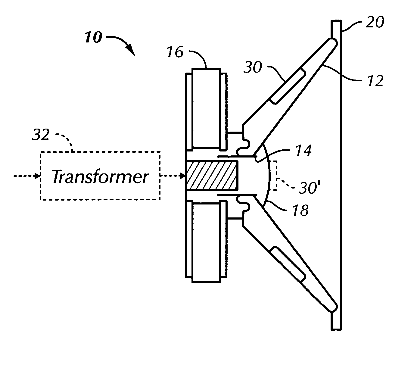
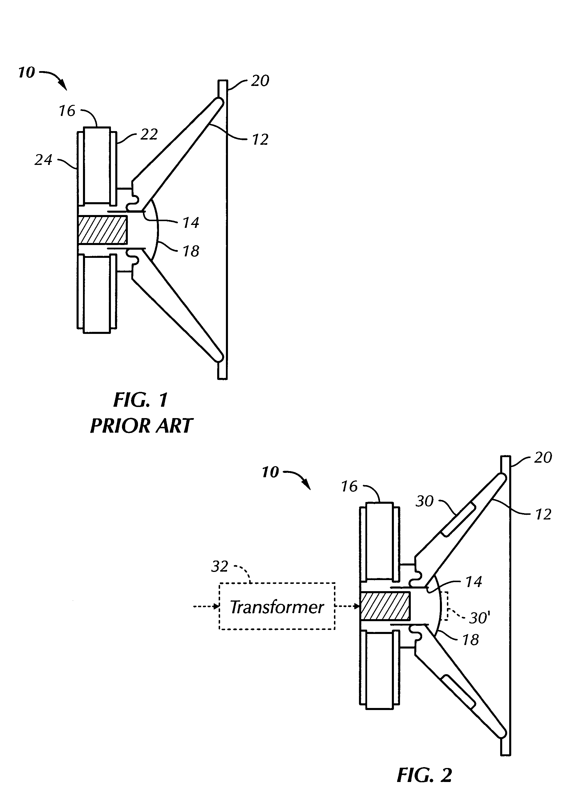
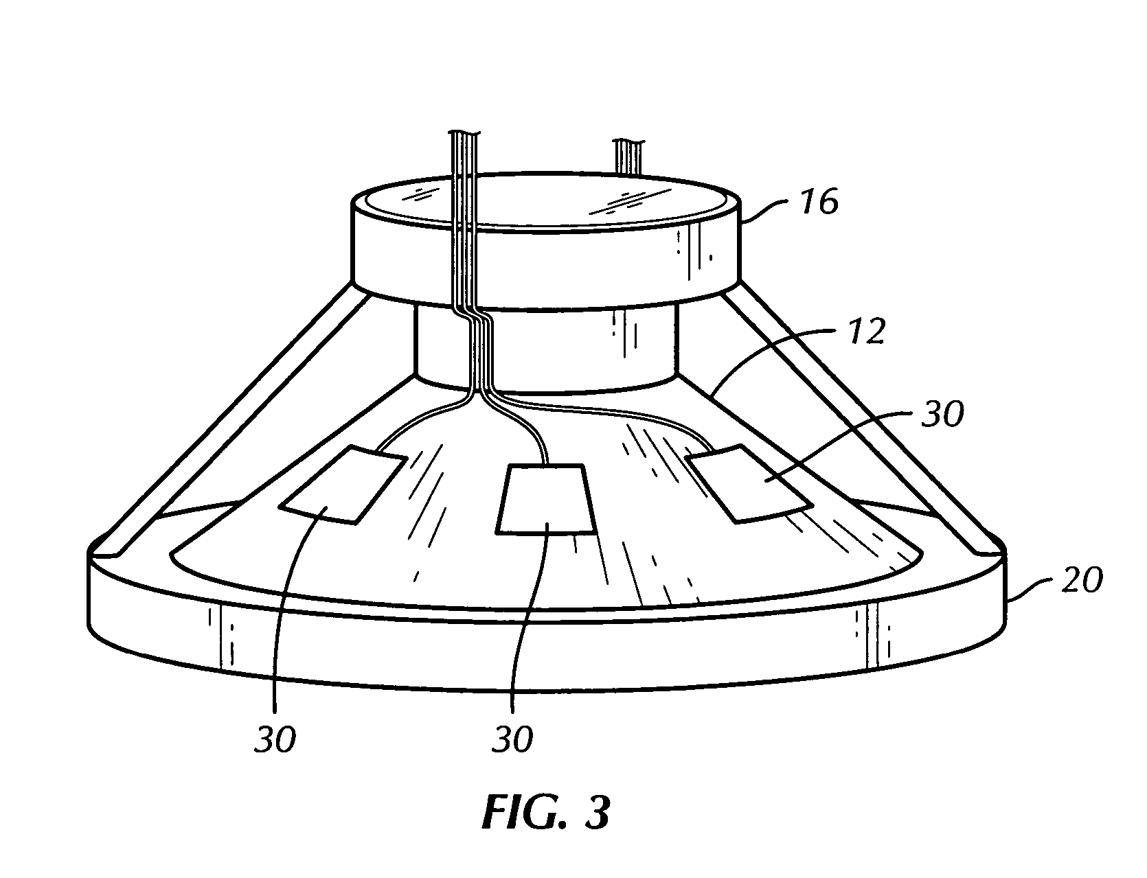
[0009] An improved audio frequency speaker comprises a speaker cone suspended for movement to generate air displacement, a voice coil having at least one winding attached to the cone and a magnet having a magnetic field. The magnet is located such that at least a portion of the coil is within the magnetic field to thereby cause the coil and the cone to move when a current from an audio frequency drive signal flows through the coil winding. The improvement comprises at least one piezoelectric actuator secured to the cone and adapted to receive the audio frequency drive signal. The at least one piezoelectric actuator moves the cone at least at higher order frequencies of the audio frequency range to thereby enhance the performance range of the speaker at the higher order frequencies so that a single speaker covers the entire audio frequency range.

Problems solved by technology

Such speakers which are driven within the breakup region have poor quality sound because the resulting resonances create audible peaks and dips in the frequency response.
Such speaker assemblies also are more prone to peaks or dips in the frequency response in the crossover region where two transducers may be operating at the same output level.
The sound quality of a piezoelectric actuator speaker is typically limited by the shape and size of the structure to which the piezoelectric material is attached.
There have been some attempts at using piezoelectric electric material as a full range speaker but the size and rigidity of the structure have presented significant hurdles.
The complex surface displacement of the driven structure resulting from the superposition of several vibration modes at a given frequency causes the pressure wave to radiate away from the structure in very complex, multi-beam patterns.

Method used


Image

  • Audio frequency speaker
  • Audio frequency speaker
  • Audio frequency speaker

Examples


Embodiment Construction

[0016] Referring now to the drawings, wherein the same reference numerals are used to designate the same components throughout the several figures, there is shown in FIG. 1 a typical prior art audio frequency transducer or speaker 10 of the type typically referred to as a woofer or mid range speaker. The speaker 10 includes a speaker cone 12 typically fabricated of a relatively flexible material such as a composite material, cardboard / paper, a polymeric material, metal or any other suitable material known to those of ordinary skill in the art. The cone 12 is suspended within a housing or surround 20, only a portion of which is shown on FIG. 1. The innermost or smaller end of the cone 12 is attached to a voice coil 14 in a manner well known to those of ordinary skill in the art. The voice coil 14, which is of a type well known in the art, includes one or more coil windings (not shown) which are electrically connected to an audio amplifier (not shown) such as a radio receiver, home th...


PUM


Abstract

An improved audio frequency speaker comprises a speaker cone suspended for movement to generate air displacement, a voice coil having at least one winding attached to the cone and a magnet having a magnetic field. The magnet is located such that at least a portion of the coil is within the magnetic field to thereby cause the coil and the cone to move when a current from an audio frequency drive signal flows through the coil winding. At least one piezoelectric actuator is secured to the cone and is adapted to receive the audio frequency drive signal. The at least one piezoelectric actuator moves the cone, at least at higher order frequencies of the audio frequency range, to thereby enhance the performance range of the speaker at the higher order frequency so that a single speaker covers the entire audio frequency range.

Description

CROSS-REFERENCE TO RELATED APPLICATIONS [0001] This application claims priority from U.S. Provisional Patent Application No. 60 / 547,209 filed Feb. 24, 2004 and entitled “Loud Speaker Including A Piezoelectric Actuator,” the entire subject matter of which is hereby incorporated herein by reference.BACKGROUND OF THE INVENTION [0002] The present invention relates to audio frequency speakers and, more particularly, to an improved audio frequency speaker for extending the frequency range of a voice coil speaker (woofer or mid range) by using one or more piezoelectric actuators mounted to one or more components of the speaker. [0003] Sound system designers have historically used electromagnetic voice coil transducers or speakers to generate air displacement. FIG. 1 is a schematic view of a typical prior art transducer 10 comprised of a suspended speaker cone 12 that is moved in and out by an attached voice coil 14 which moves through the magnetic field of a magnet 16 when current travels ...

Claims


Application Information

Patent Timeline
IPC IPC(8): H04R1/24H04R3/08H04R23/02
CPCH04R23/02H04R1/24
Inventor BIANCHINI, EMANUELE
Owner VIBRATION X DI BIANCHINI EMANUELE E C
Learn More