Rotating electric machine
A technology for rotating electrical machines and rotors, applied to electromechanical devices, electrical components, and electrical components, etc., can solve problems such as control circuit configuration limitations, increase in outer diameter of power supply units, etc., to suppress the increase in the configuration area, reduce the configuration area, The effect of improving cooling performance
- Summary
- Abstract
- Description
- Claims
- Application Information
AI Technical Summary
Problems solved by technology
Method used
Image

Examples
Embodiment approach 1
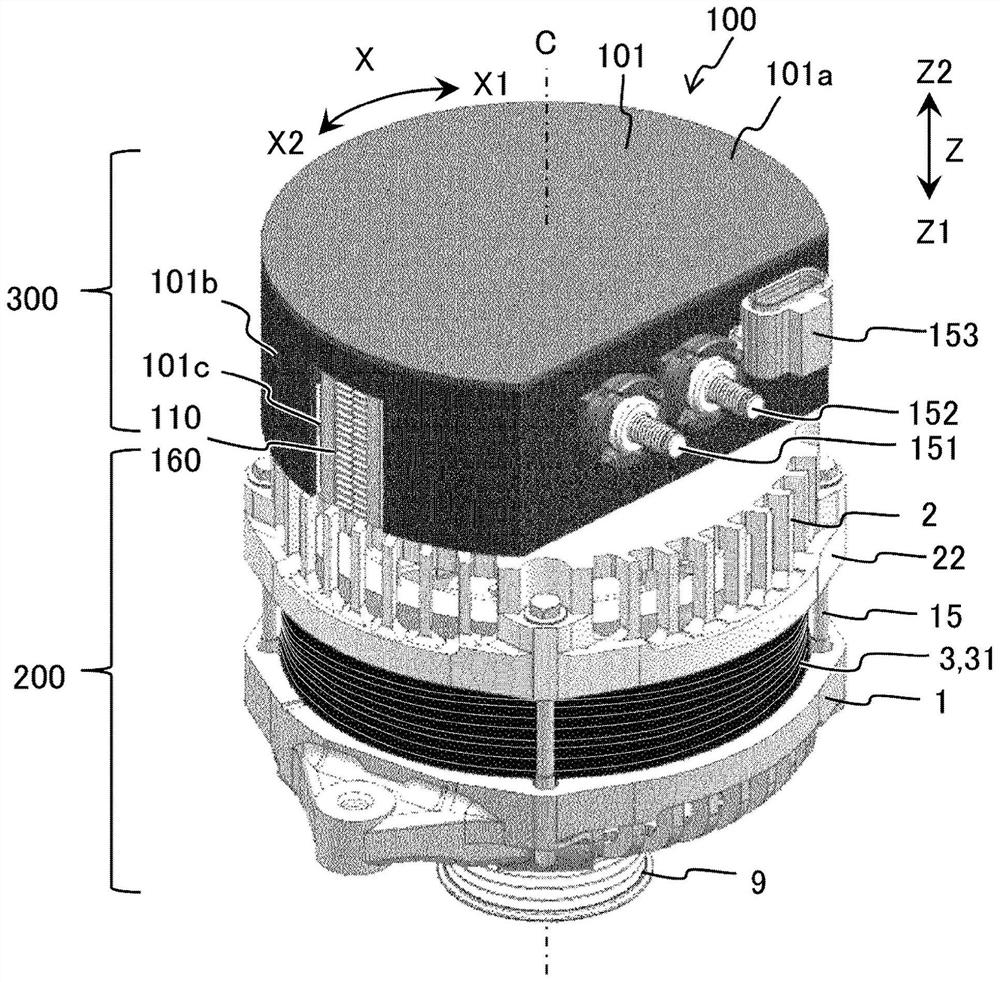
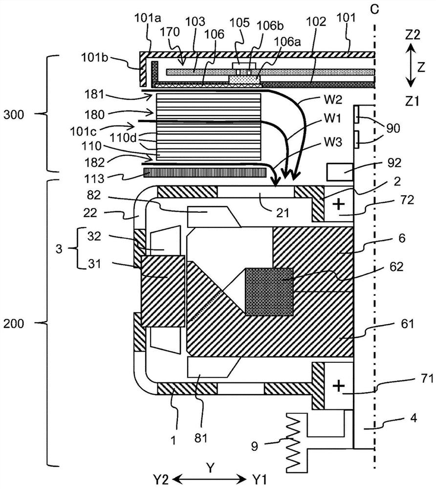
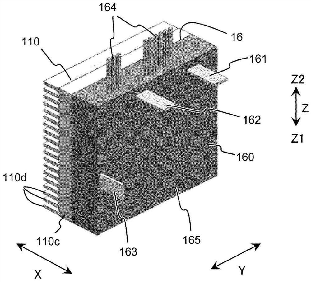
[0090] Referring to the drawings, the rotating electric machine 100 according to Embodiment 1 will be described. figure 1 is a perspective view of the rotary electric machine 100 . figure 2 This is a schematic cross-sectional view of the rotary electric machine 100 cut on a plane passing through the power unit heat dissipation member 110 and the axis C of the rotary shaft 4 . image 3 It is a perspective view of a power module 160 and the heat dissipation member 110 of the power part. Figure 4 is a circuit diagram of power semiconductor elements provided in one power module 160, Figure 5 It is to face the two power modules 160a, 160b and the two power part heat dissipation members 110a, 110b perpendicular to the radial direction Y of the central parts of the two power modules 160a, 160b and the two power part heat dissipation members 110a, 110b, etc. The sectional view of the main part that is cut.
[0091] In this application, the direction parallel to the axis C of the...
Embodiment approach 2
[0163] Next, the rotating electrical machine 100 according to Embodiment 2 will be described. The description of the same structural parts as those in the above-mentioned first embodiment will be omitted. The basic structure of the rotating electric machine 100 of this embodiment is the same as that of the first embodiment, but the structures of the housing flow path 181 and the fixing member flow path 182 are different from the first embodiment. Image 6 The radial direction Y of the central part of the two power modules 160a, 160b and the two power part heat dissipation members 110a, 110b of this embodiment is orthogonal to the two power modules 160a, 160b and the two power parts for heat dissipation A sectional view of main parts in which members 110a, 110b, etc. are cut.
[0164]
[0165] Similar to Embodiment 1, a fixed member flow path 182 is formed between the power fixing member 113 and the two power part heat sink members 110a, 110b in the axial direction. The abov...
Embodiment approach 3
[0176] Next, the rotating electrical machine 100 according to Embodiment 3 will be described. The description of the same structural parts as those in the above-mentioned first embodiment will be omitted. The basic structure of the rotating electric machine 100 of this embodiment is the same as that of the first embodiment, but the structure of the power fixing member 113 is different from that of the first embodiment. Figure 7 The radial direction Y of the central part of the two power modules 160a, 160b and the two power part heat dissipation members 110a, 110b of this embodiment is orthogonal to the two power modules 160a, 160b and the two power parts to dissipate heat. A sectional view of main parts in which members 110a, 110b, etc. are cut.
[0177]
[0178] Different from Embodiment 1, in this embodiment, the portion of power fixing member 113 disposed on the front side Z1 of the two power unit heat dissipation members 110a, 110b is formed by power fixing heat dissipa...
PUM
 Abstract
Description
Claims
Application Information
 - R&D
- Intellectual Property
- Life Sciences
- Materials
- Tech Scout
- Unparalleled Data Quality
- Higher Quality Content
- 60% Fewer Hallucinations
Browse by: Latest US Patents, China's latest patents, Technical Efficacy Thesaurus, Application Domain, Technology Topic, Popular Technical Reports.
© 2025 PatSnap. All rights reserved.Legal|Privacy policy|Modern Slavery Act Transparency Statement|Sitemap|About US| Contact US: help@patsnap.com