Automatic aligning and grinding method for drill bit

A grinding method and drill bit technology, which is applied to boring machine/drilling machine components, drilling tool accessories, drilling/drilling equipment, etc., can solve the problems of effectively saving construction costs, difficulty in combining processing speed and efficiency, large configuration space, etc. question

Active Publication Date: 2015-01-21
CIN PHOWN TECH
View PDF7 Cites 0 Cited by
  • Summary
  • Abstract
  • Description
  • Claims
  • Application Information

AI Technical Summary

Problems solved by technology

[0006] The purpose of the present invention is to overcome the problems in the above-mentioned background technology that the drill bit is transferred in a circular path and a linear path, which leads to the difficulty of both processing speed and efficiency, and occupies a large configuration space, which makes it difficult to effectively save the construction cost.

Method used


Image

  • Automatic aligning and grinding method for drill bit
  • Automatic aligning and grinding method for drill bit
  • Automatic aligning and grinding method for drill bit

Examples


Embodiment Construction

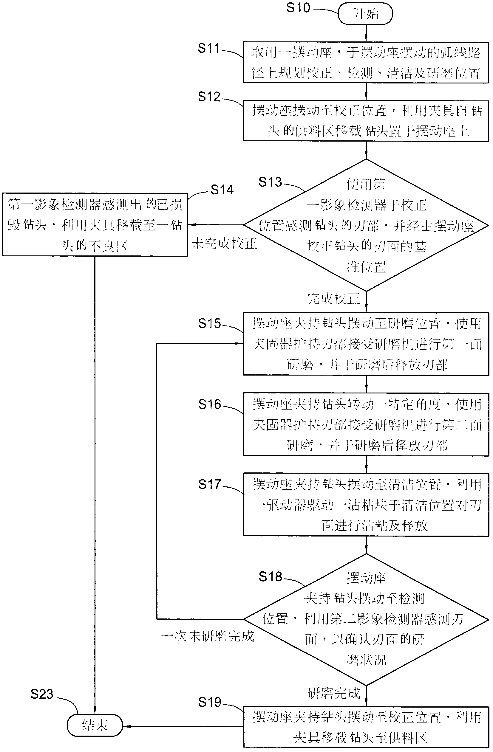
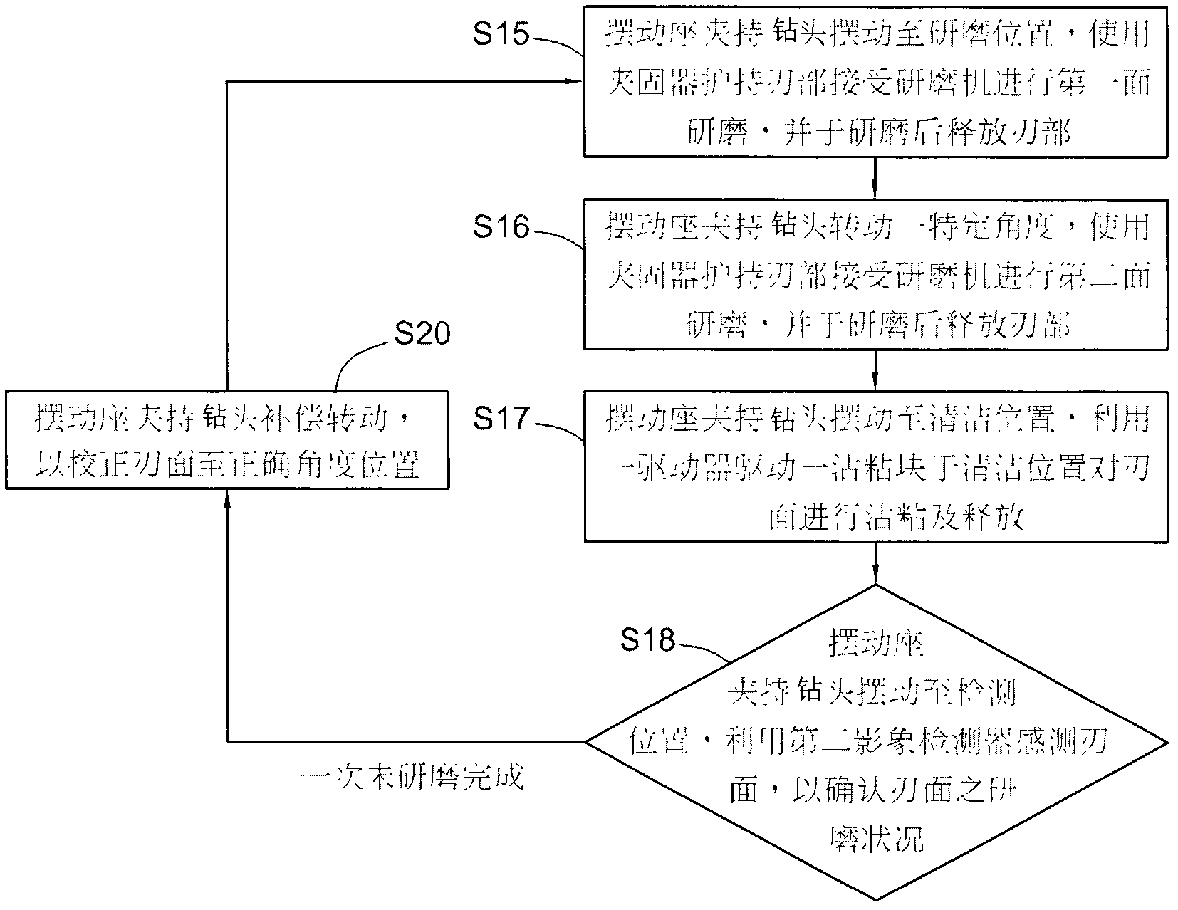
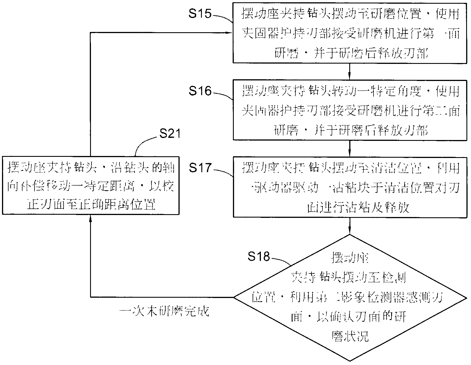
[0037] first look figure 1 Shown, reveals the flow chart of the preferred embodiment of the present invention, and coordinates figure 2 and image 3 Illustrate the automatic alignment grinding method of drill bit of the present invention, comprise following implementation steps:

[0038] In step S10, start to implement the method of the present invention.

[0039] In step S11, a swing base 1 is used, and the swing base 1 is pivotally placed near the feeding area 7 of a drill bit 9, and several drill boxes 90 capable of accommodating a plurality of drill bits 9 are arranged in the feeding area 7 , the drill bit 9 can be taken out by the drill box 90 in this implementation, and put back into the original drill box 90 after grinding, so the feed area 7 can become the feed end and outlet of the drill bit 9 in this implementation. The material end; the swing base 1 can actually be a rotary pneumatic cylinder, and the top of the rotary pneumatic cylinder has a clamping part 11 c...


PUM

PropertyMeasurementUnit
diameteraaaaaaaaaa

Abstract

The invention relates to an automatic aligning and grinding method for a drill bit. The automatic aligning and grinding method comprises the following steps: taking a swing seat, sequentially planning a correcting position, a detecting position and a grinding position on a swinging arc path of the swing seat, shifting the drill bit in a feeding area to the swing seat, receiving a correcting reference position of a first image detector at the correcting position, swinging the drill bit to the grinding position so as to be ground by a grinding machine along with the swing seat, and then swinging the drill bit to the detecting position along with the swing seat so as to confirm the grinding condition by a second image detector; when the grinding of the drill bit is confirmed to be completed, the drill bit is swung to the correcting position along with the swing seat and shifted to the feeding area; and when the grinding of the drill bit is confirmed to be not completed, the drill bit is swung to the grinding position along with the swing seat and ground by the grinding machine.

Description

technical field [0001] The invention relates to a grinding method of a drill bit, in particular to a worn micro-drill bit, and relates to the technology of automatic reference position correction and grinding of the blade surface of the micro-drill bit, as well as the image detection of correcting and grinding the blade surface machine, grinder and swing base. Background technique [0002] A micro drill is a drilling tool whose diameter can be reduced to about 0.1mm. It has been widely used in the drilling of printed circuit boards. It is easy to wear and damage, so that the drill bit is unusable; in order to prolong the service life of the drill bit, the current practice is to use a grinding machine to process and grind the blade of the worn drill bit again, so that the blade surface of the blade portion can be restored. In order to drill the correct hole diameter, before the drill bit is regrinded by the grinding machine, it is necessary to use an image (eg Charge Coupled...

Claims


Application Information

Patent Timeline
Patent Type & Authority Patents(China)
IPC IPC(8): B24B3/24
Inventor 姚志金林武庆黄兴才
Owner CIN PHOWN TECH
Why Eureka
Try Eureka