Efficient heat dissipation type power distribution cabinet

A heat-dissipating type and power distribution cabinet technology, which is applied in substation/power distribution device casing, electrical components, substation/switch layout details, etc., can solve problems affecting operation efficiency, component damage, and affecting service life, etc., to increase Installation and maintenance efficiency, lower temperature, and faster heat dissipation

Pending Publication Date: 2021-06-18
山东丽鱼家具有限公司
View PDF6 Cites 0 Cited by
  • Summary
  • Abstract
  • Description
  • Claims
  • Application Information

AI Technical Summary

Problems solved by technology

The liner for installing components inside the power distribution cabinet is fixed vertically and cannot be moved. During the later maintenance, repair and installation, the staff need to squat or bend over to work, which will easily make the staff overtired and affect the work efficiency. Power distribution The cabinet cannot dissipate heat efficiently during the heat dissipation process, and after the power distribution cabinet is placed outside, rainwater easily invades the inside of the cabinet, causing damage to components and affecting the service life

Method used


Image

  • Efficient heat dissipation type power distribution cabinet
  • Efficient heat dissipation type power distribution cabinet
  • Efficient heat dissipation type power distribution cabinet

Examples


Embodiment Construction

[0019] The present invention will be further elaborated below in conjunction with the accompanying drawings and specific embodiments.

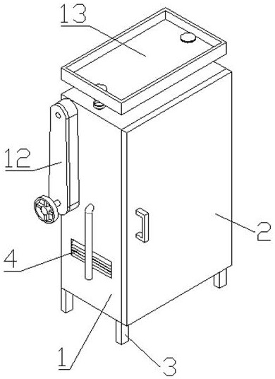
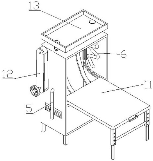
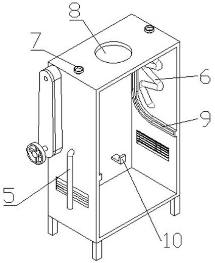
[0020] Such as Figure 1-7 As shown, a high-efficiency heat dissipation power distribution cabinet includes a cabinet body 1, a cabinet door 2, support legs 3, an air inlet 4, a drain pipe 5, a curved pipe 6, a funnel 7, an air outlet 8, a right-angle chute 9, The liner support base 10, the liner device 11, the linkage device 12, and the heat dissipation device 13 are characterized in that: the front side of the cabinet body 1 is hinged with a cabinet door 2, and the bottom of the cabinet body 1 is welded with four supporting legs 3. The lower parts of the left and right sides of the cabinet body 1 are respectively provided with air intake holes 4, the lower water pipes 5 are fixed below the left and right sides of the cabinet body 1, and the upper part of the lower water pipes 5 is connected with a curved pipe 6, and the curved pipe 6 Locate...


PUM


Abstract

The invention discloses an efficient heat dissipation type power distribution cabinet. The cabinet comprises a cabinet body, a cabinet door, supporting legs, an air inlet hole, a sewer pipe, a bent pipe, a funnel, an air outlet hole, a right-angle sliding groove, a lining plate supporting seat, a lining plate device, a linkage device and a heat dissipation device, wherein the cabinet door is hinged to the front side of the cabinet body through a hinge, and the four supporting legs are welded to the bottom of the cabinet body; air inlets are formed in the lower portions of the left side and the right side of the cabinet body respectively, the sewer pipes are fixed to the lower portions of the left side and the right side of the cabinet body, the upper portions of the sewer pipes are communicated with bent pipes, the bent pipes are located on the inner walls of the left side and the right side of the cabinet body, and funnels are welded to the tops of the bent pipes and located on the top of the cabinet body. According to the cabinet, a traditional bowing and squatting installation mode is changed, installation and maintenance efficiency of components is improved, heat transfer is carried out on the interior of the cabinet body through rainwater, the temperature in the cabinet body is reduced, and heat dissipation in the cabinet body is greatly accelerated.

Description

technical field [0001] The invention relates to a power distribution cabinet, in particular to a high-efficiency heat dissipation type power distribution cabinet. Background technique [0002] The power distribution cabinet is a general term for the motor control center. The power distribution cabinet is used in the occasions where the load is relatively scattered and there are few circuits; the motor control center is used in the occasions where the load is concentrated and there are many circuits. They distribute the electric energy of a certain circuit of the upper-level power distribution equipment to the nearest load. This level of equipment shall provide protection, monitoring and control of the load. The liner for installing components inside the power distribution cabinet is fixed vertically and cannot be moved. During the later maintenance, repair and installation, the staff need to squat or bend down to work, which will easily cause the staff to be overtired and ...

Claims


Application Information

Patent Timeline
Patent Type & Authority Applications(China)
IPC IPC(8): H02B1/56H02B1/32H02B1/28
CPCH02B1/565H02B1/32H02B1/28
Inventor 文琼
Owner 山东丽鱼家具有限公司
Why Eureka
Try Eureka