Insulator structure for power transmission and transformation project and installation method

An installation method and insulator technology, applied in the direction of suspension/strain insulators, insulators, support insulators, etc., can solve problems such as uneven distribution of insulating media, large space occupied by insulators, damage to line use and operating life, etc.

Active Publication Date: 2021-06-18
福建榕灿电气科技有限公司
View PDF13 Cites 0 Cited by
  • Summary
  • Abstract
  • Description
  • Claims
  • Application Information

AI Technical Summary

Problems solved by technology

Insulators should not fail due to various electromechanical stresses caused by changes in environmental and electrical load conditions, otherwise the insulator will not have a significant effect and will damage the service and operating life of the entire line
[0003] In the existing technology, refer to figure 1 , the structure of the insulator is that 6 through holes are evenly distributed on the circumference of the insulator, and the space on the insulator is relatively large. If the method of assembling the insulator after cutting the insulator is used, the through holes on the parts will inevitably be cut. The splicing of the holes is difficult, which will lead to uneven distribution of the insulating medium in the connector, which will affect the performance index of the connector
At the same time, because the 6 through holes of the insulator are evenly distributed, the wall of the insulator hole is thinner. If the insulator is cut and assembled, there is a risk of insufficient support strength of the insulator

Method used


Image

  • Insulator structure for power transmission and transformation project and installation method
  • Insulator structure for power transmission and transformation project and installation method
  • Insulator structure for power transmission and transformation project and installation method

Examples


Embodiment Construction

[0026] The present invention will be described in further detail below in conjunction with the accompanying drawings.

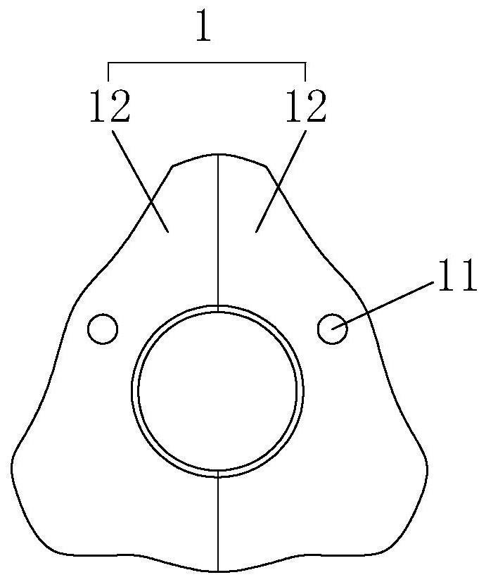
[0027] refer to figure 2 , is an insulator structure for power transmission and transformation projects disclosed by the present invention, including an insulator body 1 with a triangular end face, a press sleeve 2, a connector inner conductor 3 and a connector outer conductor 4, and two air hole 11.

[0028] Wherein, the insulator body 1 includes two insulating parts 12 that are spliced ​​together, and two air holes 11 are respectively arranged on the insulating parts 12. 11 is arranged symmetrically with the center line of the insulator body 1 .

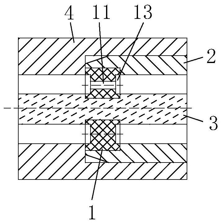
[0029] refer to image 3 , the insulator body 1 is clamped and fixed on the connector inner conductor 3, the insulator body 1 and the connector inner conductor 3 are detachably fixed in the press sleeve 2, the press sleeve 2 is detachably fixed in the connector outer conductor 4, and the connector inside Ther...


PUM


Abstract

The invention relates to an insulator structure for a power transmission and transformation project and an installation method. The insulator structure for the power transmission and transformation project comprises an insulator body with a triangular end face, a pressing sleeve, a connector inner conductor and a connector outer conductor, wherein two air holes are uniformly formed in the insulator body, the insulator body is clamped and fixed on the connector inner conductor, the insulator body and the connector inner conductor are detachably fixed in the pressing sleeve, the pressing sleeve is detachably fixed in the connector outer conductor, an outer wall of the connector inner conductor is in interference fit with an inner wall of the insulator body, and an outer wall of the insulator body is in interference fit with an inner wall of the connector outer conductor. The number of the insulator through holes is reduced to two, so the risk can be effectively avoided, the insulation support strength of the insulator is improved, and the part assembly process performance is good.

Description

technical field [0001] The invention relates to the technical field of electric power engineering, in particular to an insulator structure and installation method for power transmission and transformation engineering. Background technique [0002] Insulators are special insulation controls that can play an important role in overhead transmission lines. In the early years, insulators were mostly used on utility poles, and gradually developed into a high-voltage wire connection tower with many disc-shaped insulators hanging on one end. It is used to increase the creepage distance, usually made of glass or ceramics, and is called an insulator. Insulators should not fail due to various electromechanical stresses caused by changes in the environment and electrical load conditions, otherwise the insulator will not play a significant role and will impair the service and operating life of the entire line. [0003] In the existing technology, refer to figure 1 , the structure of th...

Claims


Application Information

Patent Timeline
Patent Type & Authority Applications(China)
IPC IPC(8): H01B17/36H01B17/38H01B17/10H01B17/16H02G7/05
CPCH01B17/36H01B17/38H01B17/10H01B17/16H02G7/05
Inventor 肖正钟郑琪
Owner 福建榕灿电气科技有限公司
Why Eureka
Try Eureka