Turbocharged engine control method and system, terminal and readable storage medium

A technology of turbocharging and control method, applied in the direction of engine control, automatic control, automatic control, etc., can solve problems such as engine or turbocharger damage, increase in boost pressure, engine knocking, etc., to reduce effective compression Effect of ratio, increased torque, and torque balance

Active Publication Date: 2021-06-18
UNITED AUTOMOTIVE ELECTRONICS SYST
View PDF5 Cites 0 Cited by
  • Summary
  • Abstract
  • Description
  • Claims
  • Application Information

AI Technical Summary

Problems solved by technology

As shown in Figure 1, once the impeller of the VGT component is stuck At a small opening (the difference between the actual VGT opening and the VGT target opening is too large), the supercharging pressure rises rapidly and exceeds the target supercharging pressure instantly. At this time, in order to protect the engine, the throttle valve starts to close, and the manifold pressure increases. Controlled but still higher than the target manifold intake pressure, so that the actual intake pressure in the engine cylinder will be higher than expected, and the maximum load exceeds the limit, resulting in damage to the engine due to knocking or pre-ignition due to excessive cylinder pressure; and , in order to keep the torque at the clutch end constant, the ignition angle is delayed to reduce the impact of the increase of the gas path torque. Due to the additional energy brought by the inertia and ignition angle delay to the variable cross-section turbocharger, the boost pressure continues to rise , the variable cross-section turbocharger will also be damaged due to overspeed due to excessive boost pressure
[0006]Currently, it takes a certain amount of time for the overboost diagnosis and stuck diagnosis of the variable geometry turbocharged engine, that is, a certain fault delay is set in order to falsely report the fault. During this period, the engine or turbocharger may be damaged due to load or speed exceeding the limit value.

Method used


Image

  • Turbocharged engine control method and system, terminal and readable storage medium
  • Turbocharged engine control method and system, terminal and readable storage medium
  • Turbocharged engine control method and system, terminal and readable storage medium

Examples


Embodiment Construction

[0039] The specific implementation manner of the present invention will be described in more detail below with reference to schematic diagrams. The advantages and features of the present invention will be more apparent from the following description. It should be noted that all the drawings are in a very simplified form and use imprecise scales, and are only used to facilitate and clearly assist the purpose of illustrating the embodiments of the present invention.

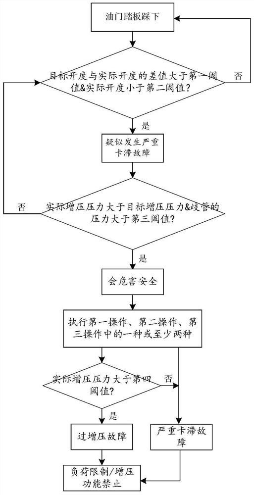
[0040] figure 2 A flow chart of a control method for a turbocharged engine provided in this embodiment. Such as figure 2As shown, this embodiment provides a control method for a turbocharged engine, and the turbocharged engine includes a connected turbocharger and an engine. The control method of the turbocharged engine is used to protect the turbocharger and / or the safety of the engine, avoid damage to the turbocharged engine, and prolong the life of the turbocharged engine.

[0041] In this embodiment, th...


PUM


Abstract

The invention provides a turbocharged engine control method and system, a terminal and a readable storage medium. When a turbocharger is suspected to have a serious clamping stagnation fault and the serious clamping stagnation fault can endanger the safety of a turbocharged engine, one or at least two of the following three operations are executed. According to the first operation, the opening degree of a throttle valve of the engine is reduced, then the load in a cylinder of the engine and the maximum combustion explosion pressure are reduced, and the engine can be protected. According to the second operation, the minimum ignition angle of the engine is increased, separate-cylinder fuel cut-off is conducted on the engine, the torque can be increased by increasing the minimum ignition angle of the engine, the torque can be reduced by conducting separate-cylinder fuel cut-off on the engine, and therefore torque balance is achieved, the output torque is kept unchanged, and the turbocharger can be protected. According to the third operation, an intake valve of the engine is closed in advance, the engine enters a Miller cycle, the effective compression ratio can be decreased, knocking or preignition can be avoided, and the engine and the turbocharger can be protected at the same time.

Description

technical field [0001] The present invention relates to the technical field of engines, in particular to a control method, system, terminal and readable storage medium of a turbocharged engine. Background technique [0002] With the development of technology, people have more and more stringent requirements on the performance of automobile engines, not only requiring them to have strong power, but also to have higher efficiency and clean emissions. People's requirements for engine performance require that the engine can achieve a relatively efficient working state under various working conditions. gas requirements. [0003] In order to meet the air intake requirements of the engine, people hope to make the engine air intake "variable" through related designs to meet the air intake requirements under different working conditions, such as the well-known variable valve timing / lift technology, The variable intake manifold technology is developed based on this, and the variable...

Claims


Application Information

Patent Timeline
Patent Type & Authority Applications(China)
IPC IPC(8): F02B37/00F02B37/12F01L13/00F02D13/02F02P5/145
CPCF02B37/00F02B37/12F01L13/0015F02P5/145F02D13/0226Y02T10/12
Inventor 庄兵骆海建倪传钦
Owner UNITED AUTOMOTIVE ELECTRONICS SYST
Why Eureka
Try Eureka