
Construction method for synchronous formwork supporting and concrete pouring of bottom plate and top plate of cast-in-place pipe gallery

A technology of pouring concrete and construction methods, which is applied in the field of concrete pouring, and can solve the problems of large investment in steel bar brackets/steel plates, inconvenient lifting and installation of steel plates, and difficult control of steel plate plane leveling, etc., and achieves wide application range, small loss, The effect of no safety hazard

Inactive Publication Date: 2021-06-18
CHINA 22MCC GROUP CORP
View PDF4 Cites 3 Cited by
  • Summary
  • Abstract
  • Description
  • Claims
  • Application Information

AI Technical Summary

Problems solved by technology

The above-mentioned method of vertically supporting the formwork with the reinforcement grid on the bottom plate has limitations: (1) The lifting and installation of the steel plate is inconvenient, and the fixing is difficult; (2) The plane leveling of the steel plate is difficult to control and the precision is low; (3) There are many implementation processes, The construction period is long; (4) The investment of steel support / steel plate is large and the cost is high; (5) The support effect is poor and the safety hazard is large

Method used


Image

  • Construction method for synchronous formwork supporting and concrete pouring of bottom plate and top plate of cast-in-place pipe gallery
  • Construction method for synchronous formwork supporting and concrete pouring of bottom plate and top plate of cast-in-place pipe gallery

Examples


Embodiment Construction

[0017] In order to fully understand the purpose, features and effects of the present invention, the present invention will be described in detail through the following specific embodiments, but the present invention is not limited thereto.

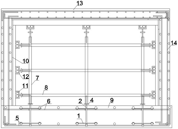
[0018] see figure 1 and figure 2 , the construction method of a kind of cast-in-place pipe rack bottom plate and top plate synchronous formwork pouring concrete provided by the present invention, carry out according to the following steps:

[0019] S1. Make the vertical support device: Weld the hooks facing downward at the four end points of the lower cross support rod 1, weld the vertical rod 2 on the midpoint of the lower cross support rod 1, and weld the upper cross in the middle of the vertical rod 2 The four ends of the support rod 3 and the upper cross support rod 3 are respectively welded with upwardly facing hooks; the upper part of the vertical rod 2 is fixedly welded with the horizontal support rod 4, and the height of the hori...


PUM


Abstract

The invention discloses a construction method for synchronous formwork supporting and concrete pouring of a bottom plate and a top plate of a cast-in-place pipe gallery, and relates to the technical field of concrete pouring. According to the method, the supporting strength of the concrete bottom plate is improved through a vertical supporting device, a formwork supporting system is erected on the bottom plate, the top plate and the side walls, meanwhile, concrete pouring and curing are carried out on the bottom plate, the top plate and the side walls, the formwork supporting system is disassembled after curing is completed, a vertical rod and a horizontal supporting rod on the upper surface of the bottom plate concrete are partially cut off, and simultaneous pouring operation is completed. According to the method, the vertical supporting device is easy to manufacture and convenient to install; the number of procedures is small, and the efficiency is high; the construction period of the supporting system is short, and the installation speed is high; the loss is small, and the construction cost is low; the supporting system does not need to be welded with bottom plate steel bars, and the application range is wide; the stress balance of the side walls is good, and the stability of the supporting frame is good; the supporting effect is good, and potential safety hazards are avoided; and the bottom plate, the top plate and the side walls are synchronously implemented, no construction joint exists, the integrity is good, the anti-seepage effect is good, and the construction period is greatly shortened.

Description

technical field [0001] The invention relates to the technical field of concrete pouring, in particular to a construction method for synchronous formwork pouring of a bottom plate and a top plate of a cast-in-situ pipe gallery. Background technique [0002] In the existing technology, the construction of the general cast-in-place pipe gallery is divided into pouring the bottom slab concrete first, then binding the side wall and roof reinforcement and supporting the side wall and roof formwork, and simultaneously pouring the side wall and roof concrete, or pouring the bottom slab concrete first. Finally, tie the side wall reinforcement and support the side wall formwork and then pour the side wall concrete, and finally support the roof formwork and tie the roof reinforcement and then pour the roof concrete. However, sometimes the construction period has to be shortened due to tight construction schedules or weather reasons, and the upper and lower concrete slabs are poured at ...

Claims


Application Information

Patent Timeline
Patent Type & Authority Applications(China)
IPC IPC(8): E02D29/045E02D15/02E02D31/02
CPCE02D29/10E02D15/02E02D31/02
Inventor 韩春
Owner CHINA 22MCC GROUP CORP
Learn More