
Patsnap Eureka
For R&D, Patsnap Eureka makes reading and utilizing patents & technical documents easy.
Patsnap Eureka AIR
Designed for self-driven R&D workflows. Generate viable solutions, solve complex R&D challenges, empower your innovation with AI.

Patsnap Eureka Materials
Designed for material experts only. Revolutionize your material R&D, from search, analyze, to developing new materials.

TechResearch
Generate reliable direction feasibility study reports for your R&D in just a few steps.

TechSeek
Discover and master advanced knowledge NOW. Basics, ideas, possibilities, all at once.

TechMind
As an expert in R&D Theories, TechMind can generates customized viable solutions instantly.

TechRisk
Analyze your overall solution with one click, know your potential R&D risks in advance.

TechMonitor
Get weekly tech updates, stay abreast of the latest tech innovations and key insights.
Calibration system and method applied to ultrasonic gas meter
A technology for calibrating systems and gas meters, applied in testing/calibrating devices, measuring devices, instruments, etc., can solve problems such as time-consuming, easily lost pulses, high cost, etc., to improve accuracy, reduce time-consuming, and avoid lost errors Effect
- Summary
- Abstract
- Description
- Claims
- Application Information
AI Technical Summary
Problems solved by technology
Method used
Image

Examples
Embodiment 1
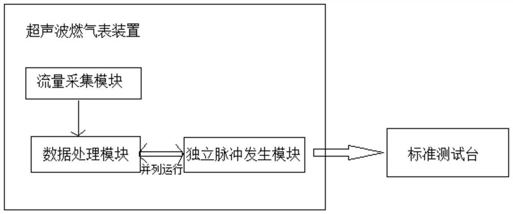
[0050] This embodiment provides a calibration system applied to an ultrasonic gas meter, including a standard test bench and an ultrasonic gas meter device. The ultrasonic gas meter device includes: a flow acquisition module, a data processing module and an independent pulse generation module;
[0051] The flow collection module collects gas flow rate data in the metering pipeline every t seconds;
[0052] The data processing module formulates a pulse sending strategy according to the current gas flow rate data and the current gas flow level, and at the same time, the independent pulse generating module sends pulses to the standard test bench according to the pulse sending strategy, and the independent pulse generating module and the data processing module run in parallel;
[0053] The standard test bench calculates the measured flow data based on all pulses received during the calibration measurement time. The standard test bench compares the measured flow data with the standa...
Embodiment 2
[0072] A calibration method applied to an ultrasonic gas meter is applied to a calibration system applied to an ultrasonic gas meter in Embodiment 1, comprising the following steps;
[0073] During the calibration measurement time, the gas flow rate data in the metering pipeline is collected every t seconds;
[0074] According to the current gas flow rate data and the current gas flow level, the pulse sending strategy is formulated, and the pulse is sent to the standard test bench according to the pulse sending strategy;
[0075] Calculate the measured flow data based on all pulses received within the calibration measurement time, compare the measured flow data with the standard flow data to obtain the error value of the ultrasonic gas meter, and calibrate the ultrasonic gas meter.
[0076] The standard test bench judges whether the error value of the ultrasonic gas meter is within the preset range,
[0077] If not, send the corresponding standard flow data to the ultrasonic ...
PUM
 Abstract
Description
Claims
Application Information
 - R&D Engineer
- R&D Manager
- IP Professional
- Industry Leading Data Capabilities
- Powerful AI technology
- Patent DNA Extraction
Browse by: Latest US Patents, China's latest patents, Technical Efficacy Thesaurus, Application Domain, Technology Topic, Popular Technical Reports.
© 2024 PatSnap. All rights reserved.Legal|Privacy policy|Modern Slavery Act Transparency Statement|Sitemap|About US| Contact US: help@patsnap.com