
Automatic one-way valve element assembling machine

An automatic group, one-way valve technology, used in metal processing, metal processing equipment, manufacturing tools, etc., can solve the problems of reducing elasticity and load capacity, manual assembly defects, leakage, inability to adapt, etc., to achieve the effect of improving positioning accuracy

Inactive Publication Date: 2021-06-15
李德水
View PDF0 Cites 0 Cited by
  • Summary
  • Abstract
  • Description
  • Claims
  • Application Information

AI Technical Summary

Problems solved by technology

For a long time, the assembly of the check valve spool has relied on manual operation, which cannot meet the needs of increasing technological development at all, and the disadvantages of manual assembly are increasingly exposed.
It is necessary to use automatic equipment to realize the automatic operation of the check valve spool; the jaws of the existing check valve spool automatic assembly machine grab the spool and the spring for grasping and welding, because the spring is a single superimposed structure, when the spring It is easy to bend on the inside of the claw with the minimum stiffness, and has a large tensile stiffness and bending stiffness in the other direction, so that the outer circumference of the spring will match its own stiffness when it is welded with the valve core. A disjointed power is brought to the spring limited and pressed at the end of the claw, which makes it difficult for the center of the valve core and the spring to communicate accurately on a concentric circle, which not only affects the appearance of the finished check valve, but also greatly reduces its performance. Elasticity and load capacity

Method used


Image

  • Automatic one-way valve element assembling machine
  • Automatic one-way valve element assembling machine
  • Automatic one-way valve element assembling machine

Examples


Embodiment 1

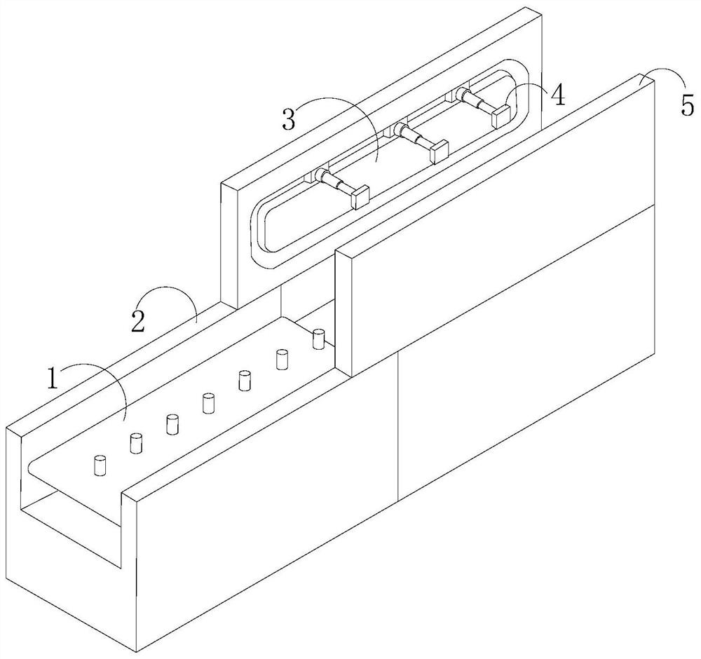
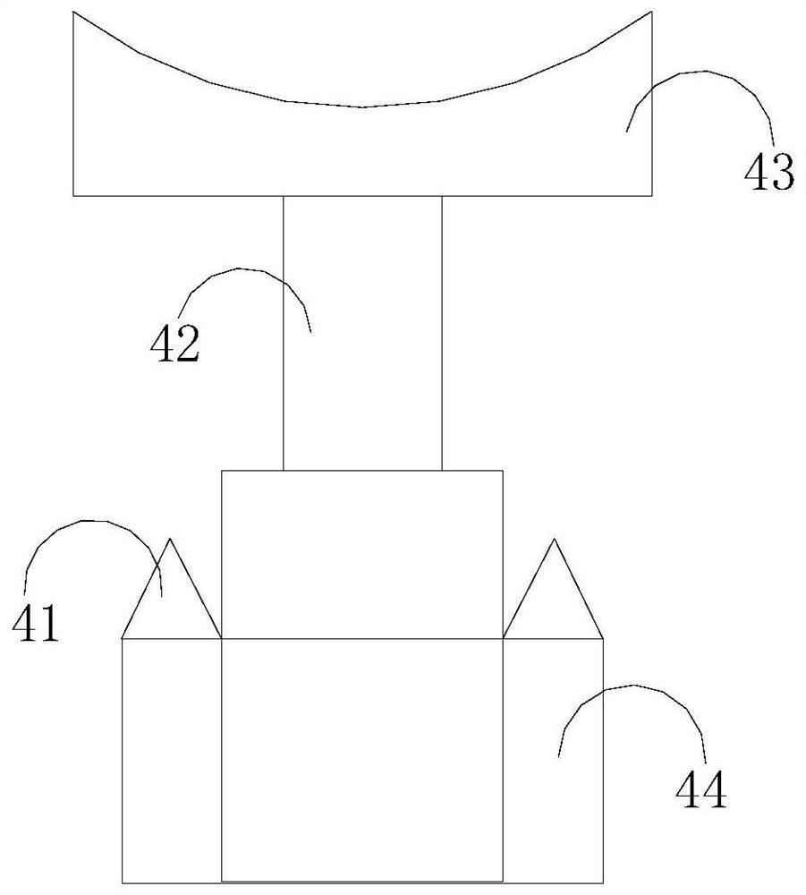
[0026] Such as Figure 1-Figure 3 As shown, the present invention provides an automatic assembling machine for a one-way valve core, the structure of which includes a conveyor belt 1, a base 2, a fixed plate 3, claws 4, and a side plate 5, and the conveyor belt 1 is fixedly connected to one end of the base 2 , the other end of the base 2 is welded with two side plates 5, the inside of the side plate 5 is welded with a fixed plate 3, and a claw 4 is installed on the fixed plate 3, and the claw 4 includes buckles 41. Connecting column 42, clamping mechanism 43, card edge handle 44, said button teeth 41 are provided with two, respectively fixedly connected on both sides of card edge handle 44, and the middle part of said card edge handle 44 is inserted and connected with connecting column 42, and the card edge 44 is socketed and connected between the fixed plate 3 and the side plate 5, and the clamping mechanism 43 is installed on the top of the connecting column 42, and the clam...

Embodiment 2

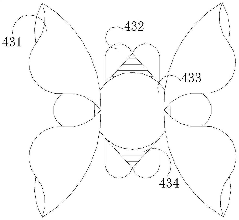
[0028] Such as Figure 4-Figure 7 As shown, on the basis of Embodiment 1, the present invention combines the mutual cooperation of the following structural components. The pipe collar 431 includes a hinge 311, a top block 312, an outer limiting piece 313, a sloping plate 314, and a collar 315. The hinge 311 is fixedly connected to one end of the inclined plate 314, and the other end of the inclined plate 314 is hingedly connected to the outer circumference of the collar 315. Both sides of the top block 312 are provided with outer limiting pieces 313. The external indirect cooperation of the inlet body 434 is convenient for the indirect auxiliary pipe collar 431 to deform toward both sides of the spring, and the additional internal force generated ensures the bearing capacity of the overall structure. Strip 333, pressure bag 334, booster 335, socket cavity 336, the card point hook 331 is a semicircular structure, and is engaged with the inner circumference of the collar 315 thr...


PUM


Abstract

The invention discloses an automatic one-way valve element assembling machine. The automatic one-way valve element assembling machine structurally comprises a conveying belt, a base, a fixing plate, a clamping jaw and side plates, the conveying belt is connected to one end of the base, the two side plates are connected to the other end of the base, the fixing plate is connected to the side plates, the clamping jaw is installed on the fixing plate, and a clamping mechanism is provided with a pipe hoop and an auxiliary device. The pipe hoop and the auxiliary device are matched on a progressive body, when the outer circumference of a spring is welded to a valve element, the bottom of the spring can be bent in the auxiliary device due to pressing and rotate and hook in the auxiliary device, the auxiliary device is driven to run in and drive the pipe hoop to rotate upwards to be attached to the outer circumference of the spring, and the risk that the spring is disjointed during welding is avoided.

Description

technical field [0001] The invention relates to the field of automatic machinery, in particular to an automatic assembly machine for a check valve core. Background technique [0002] Check valves have been widely used in hydraulic and pneumatic transmissions. The check valve spool includes a spool and a spring. Due to the small size of the spool and spring. For a long time, the assembly of the check valve spool has relied on manual operations, which cannot meet the needs of increasing technological development at all, and the disadvantages of manual assembly are increasingly exposed. It is necessary to use automatic equipment to realize the automatic operation of the check valve spool; the jaws of the existing check valve spool automatic assembly machine grab the spool and the spring for grasping and welding, because the spring is a single superimposed structure, when the spring It is easy to bend on the inside of the claw with the minimum stiffness, and has a large tensile...

Claims


Application Information

Patent Timeline
Patent Type & Authority Applications(China)
IPC IPC(8): B23P19/04
CPCB23P19/04B23P19/048
Inventor 余春生
Owner 李德水
Learn More