


Quick Research
Generate reliable direction feasibility study reports for your R&D in just a few steps.

Technical Q&A
Discover and master advanced knowledge NOW. Basics, ideas, possibilities, all at once.

Find Solutions
As an expert in R&D theories, this can generate solutions to your technical problems instantly.

Evaluate Feasibility
Analyze your overall solution with one click, know your potential R&D risks in advance.

Monitor Landscape
Get weekly tech updates, stay abreast of the latest tech innovations and key insights.
Combined transformer
A transformer and combined technology, applied in the field of transformers, can solve problems such as reducing the production cost of transformers, and achieve the effects of ensuring stability, convenient disassembly and integration, and simple structure
- Summary
- Abstract
- Description
- Claims
- Application Information
AI Technical Summary
Problems solved by technology
Method used
Image


Examples
Embodiment 1
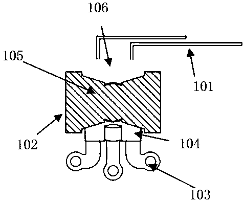
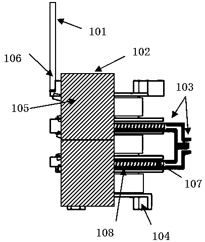
[0017] Such as image 3 , figure 1 , figure 2 , Figure 5 , Figure 6 , Figure 7 As shown, the skeleton 104 and the magnetic core 105 of the present invention are in the shape of PQ, three winding slots are processed on the outer wall of the skeleton 104, a skeleton hole 109 is processed in the middle of the skeleton 104, and the skeleton 104 between adjacent winding slots is also processed There is an annular limiting hole 108 parallel to the winding slot, thereby forming a first limiting hole and a second limiting hole, and two annular copper sheets 103 are respectively inserted in the first limiting hole and the second limiting hole , the ring-shaped copper sheet 103 is processed with a broken seam 113, and the ring-shaped copper sheet at both ends of the broken seam 113 is respectively processed with a direct wire terminal 111 and a bent wire terminal 112, and the end of the direct wire terminal 111 and the end of the bent wire terminal 112 Parts are processed with ...
Embodiment 2
[0020] Such as Figure 4 , figure 1 , figure 2 , Figure 5 , Figure 6 , Figure 7 As shown, the skeleton 104 and the magnetic core 105 of the present invention are in the shape of PQ, three winding slots are processed on the outer wall of the skeleton 104, a skeleton hole 109 is processed in the middle of the skeleton 104, and the skeleton 104 between adjacent winding slots is also processed There is an annular limiting hole 108 parallel to the winding slot, thereby forming a first limiting hole and a second limiting hole, and two annular copper sheets 103 are respectively inserted in the first limiting hole and the second limiting hole , the ring-shaped copper sheet 103 is processed with a broken seam 113, and the ring-shaped copper sheet at both ends of the broken seam 113 is respectively processed with a direct wire terminal 111 and a bent wire terminal 112, and the end of the direct wire terminal 111 and the end of the bent wire terminal 112 Parts are processed with...
PUM
 Abstract
Description
Claims
Application Information
 - R&D Engineer
- R&D Manager
- IP Professional
- Industry Leading Data Capabilities
- Powerful AI technology
- Patent DNA Extraction
Browse by: Latest US Patents, China's latest patents, Technical Efficacy Thesaurus, Application Domain, Technology Topic, Popular Technical Reports.
© 2024 PatSnap. All rights reserved.Legal|Privacy policy|Modern Slavery Act Transparency Statement|Sitemap|About US| Contact US: help@patsnap.com