
Current detection circuit with leading edge blanking

A cutting-edge blanking and rectification circuit technology, applied in electrical components, output power conversion devices, and AC power input into DC power output, etc., can solve the limitation of application scope, fixed time of cutting-edge blanking circuit, and can not meet the requirements of switching power supply. Diversified design and other issues to achieve the effect of improving filter bandwidth and simple circuit

Pending Publication Date: 2021-06-11
SICHUAN SHENGHUA POWER TECH CO LTD
View PDF1 Cites 0 Cited by
  • Summary
  • Abstract
  • Description
  • Claims
  • Application Information

AI Technical Summary

Problems solved by technology

Although this circuit can suppress the peak voltage of the gate-source forward drive of the MOS tube, its application range is relatively limited and cannot meet the diversified designs of today's switching power supplies.
[0004] Although some PWM ICs on the market have a built-in leading edge blanking circuit, the time of this leading edge blanking circuit is relatively fixed, and the application range is relatively limited, which cannot meet the diversified designs of today's switching power supplies.

Method used


Image

  • Current detection circuit with leading edge blanking
  • Current detection circuit with leading edge blanking
  • Current detection circuit with leading edge blanking

Examples


Embodiment Construction

[0020] In order to have a clearer understanding of the technical features, purposes and effects of the present invention, the specific implementation manners of the present invention will now be described with reference to the accompanying drawings.

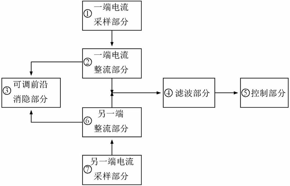
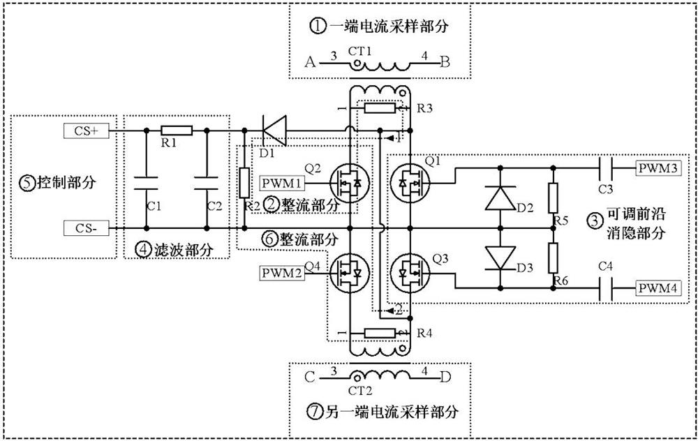
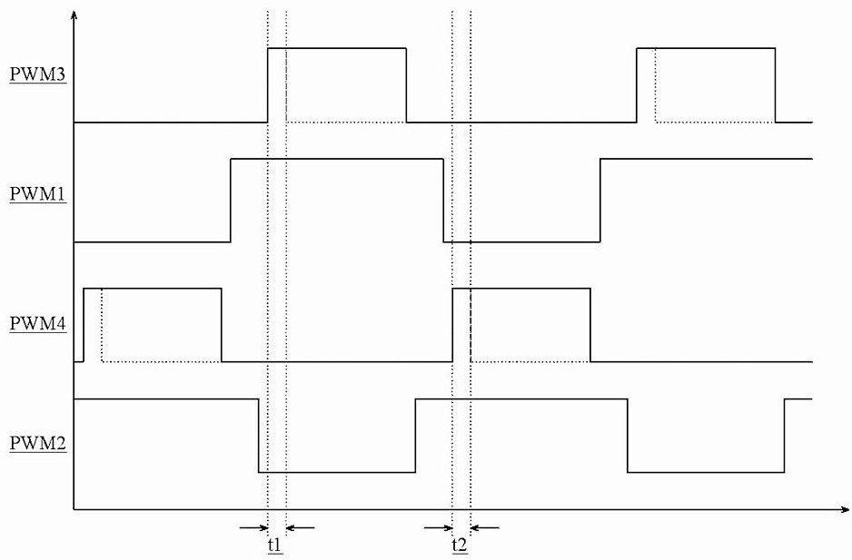
[0021] In this example, if figure 1 As shown, a current detection circuit with leading edge blanking includes a sampling circuit, a rectifier circuit, an adjustable leading edge blanking circuit, a filter circuit and a control circuit; the sampling circuit includes a sampling circuit A and a sampling circuit B; the two input terminals of the rectification circuit They are respectively connected to the acquisition circuit A and the acquisition circuit B, and the output terminals of the rectification circuit are respectively connected to the two input terminals of the adjustable leading edge blanking circuit and the input terminal of the filter circuit; the output terminal of the filter circuit is connected to the input terminal of ...


PUM


Abstract

The invention discloses a current detection circuit with leading edge blanking. The current detection circuit comprises a sampling circuit, a rectifying circuit, an adjustable leading edge blanking circuit, a filter circuit and a control circuit; the sampling circuit comprises a sampling circuit A and a sampling circuit B; two input ends of the rectification circuit are respectively connected with the acquisition circuit A and the acquisition circuit B, and an output end of the rectification circuit is respectively connected with two input ends of the adjustable leading edge blanking circuit and an input end of the filter circuit; and the filter circuit output end is connected with the control circuit input end. The current detection circuit is not limited by whether an IC has a current leading edge blanking function or not any more, the CS filtering bandwidth is improved, real current signals can be sampled better, and the circuit adopts conventional discrete devices, does not need special design, is simple and is easy to realize localization.

Description

technical field [0001] The invention relates to the field of circuit leading edge blanking, in particular to a current detection circuit with leading edge blanking. Background technique [0002] Most topological circuits of switching power supplies often fail to work properly or even fail due to unreasonable current detection. Due to the parasitic parameters of power devices and PCB trace interference, whether it is resistance sampling or current transformer sampling, there will be a peak current when the MOS tube is turned on. If this spike is not dealt with, it will participate in PWM regulation under current mode control and cause the circuit to fail to operate normally, and it may also trigger overcurrent protection under voltage mode control to cause abnormal faults. [0003] The patent with the application number CN201821219163.9 discloses a MOS tube drive circuit that suppresses driving voltage spikes, including a push-pull circuit, an RCD snubber circuit, a gate res...

Claims


Application Information

Patent Timeline
IPC IPC(8): H02M1/088H02M1/32H02M7/217
CPCH02M1/088H02M1/32H02M7/217
Inventor 谢沁坤杨宇帆李宏程
Owner SICHUAN SHENGHUA POWER TECH CO LTD
Learn More