Deep extraction device for flue gas waste heat of thermal power plant

A flue gas waste heat and deep extraction technology, applied in the direction of exhaust gas equipment, heat exchanger type, climate sustainability, etc., can solve the problems of waste, heat loss, high equipment cost, etc., achieve low equipment cost, improve thermal efficiency, structure simple effect

Pending Publication Date: 2021-06-11
NORTH CHINA POWER ENG
View PDF0 Cites 2 Cited by
  • Summary
  • Abstract
  • Description
  • Claims
  • Application Information

AI Technical Summary

Problems solved by technology

[0003] However, after passing through the existing heat exchange equipment such as the smoke cooler, the flue gas obtained still contains a small amount of waste heat that can be recycled. Exhaust, heat loss causes waste

Method used


Image

  • Deep extraction device for flue gas waste heat of thermal power plant
  • Deep extraction device for flue gas waste heat of thermal power plant

Examples


Embodiment Construction

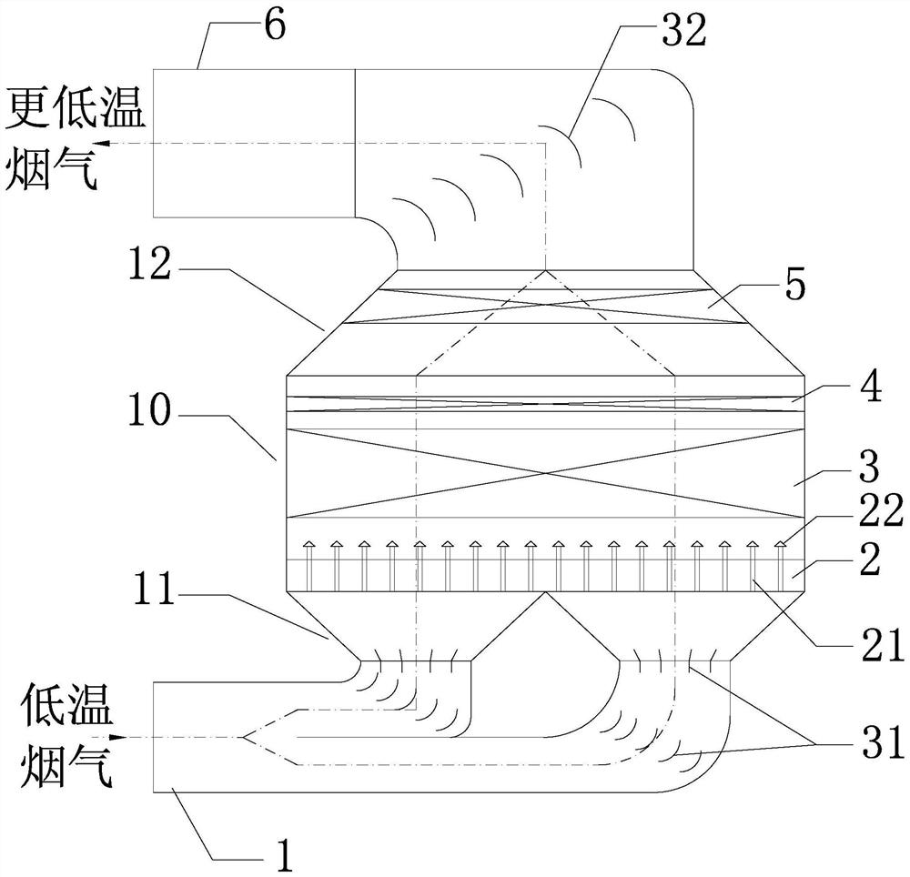
[0017] The invention belongs to a deep extraction device for flue gas waste heat in a thermal power plant, which is arranged at a low-temperature flue gas pipeline.

[0018] Specifically, the extraction device includes a hollow absorption tower 10, and the inlet flue 1 of the absorption tower 10 is connected to a low-temperature flue gas pipeline. The outlet of the inlet flue 1 can be as figure 1 As shown, it is divided into 2 paths, which are connected to the bottom of the absorption tower 10. The connecting part of the inlet flue 1 and the absorption tower 10 is the first variable diameter section 11, where the diameter gradually increases along the direction of the flue gas and is funnel-shaped. Several first deflectors 31 can be arranged at suitable positions in the inlet flue 1 , and the funnel-shaped arrangement cooperates with the first deflectors 31 so that the flue gas can enter the absorption tower 10 evenly.

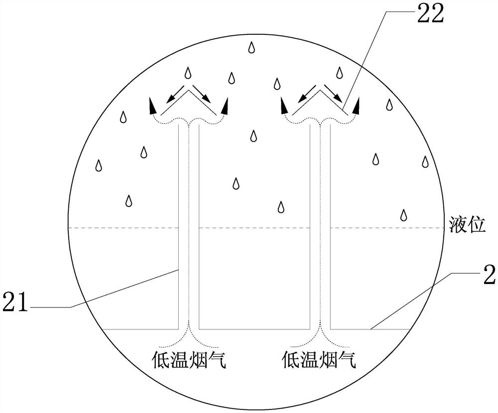
[0019] The bottom of the absorption tower 10 is provide...


PUM


Abstract

The invention provides a deep extraction device for flue gas waste heat of a thermal power plant. The device comprises an absorption tower, wherein an inlet flue of the absorption tower is connected to a low-temperature flue gas pipeline, at least one outlet of the inlet flue communicates with the bottom of the absorption tower, a liquid collection disc is arranged at the bottom in the absorption tower, filler is arranged in the middle of the absorption tower, a circulating water distributor is arranged at the top of the absorption tower, the liquid collection disc is a gas raising pipe liquid collection disc, a flue gas outlet of the absorption tower communicates with an outlet flue, and a mist eliminator is arranged at the flue gas outlet of the absorption tower. According to the deep extraction device for the flue gas waste heat, direct contact heat exchange between circulating water and low-temperature flue gas can be utilized, waste heat in low-temperature flue gas can be effectively recycled, the heat efficiency of a unit is improved, the requirement for environmental protection is met, and meanwhile the structure is simple, and the equipment cost is low.

Description

technical field [0001] The invention is a waste heat extraction device suitable for low-temperature flue gas treatment in thermal power plants. Background technique [0002] Existing coal-fired units or gas-steam combined cycle units are discharged on the back flue of the boiler. In addition to desulfurization, denitrification and other equipment, different heat exchange equipment will be installed according to the scale of the power plant and the actual engineering situation to recover the heat contained in the flue gas. Reuse can improve the thermal efficiency of the unit and reduce the temperature of the flue gas when it is discharged, which meets the current requirements for environmental protection. [0003] However, after passing through the existing heat exchange equipment such as the smoke cooler, the flue gas obtained still contains a small amount of waste heat that can be recycled. If it is discharged, the heat will be lost and cause waste. [0004] How to effect...

Claims


Application Information

Patent Timeline
IPC IPC(8): F23J11/00F23J13/00F23J15/06F28C1/16F28F25/08F28F25/04
CPCF23J11/00F23J13/00F23J15/06F28C1/16F28F25/04F28F25/08Y02E20/30
Inventor 鞠付栋衡德峰孙永斌牛苗任
Owner NORTH CHINA POWER ENG
Why Eureka
Try Eureka