Eureka AIR delivers breakthrough ideas for toughest innovation challenges, trusted by R&D personnel around the world.

Gear machining and grinding equipment and operation method thereof

A technology of gears and equipment, applied in the field of gear processing and grinding equipment, can solve the problems of low grinding efficiency, influence of grinding accuracy, single movement mode of grinding roller, etc., and achieve the effect of increasing grinding effect, good grinding uniformity and various movement modes.

Inactive Publication Date: 2021-06-11
安徽省小小科技股份有限公司
View PDF4 Cites 2 Cited by
  • Summary
  • Abstract
  • Description
  • Claims
  • Application Information

AI Technical Summary

Problems solved by technology

[0003] The existing gear processing and grinding equipment has a single movement mode of the grinding roller, which limits the movement range of the grinding roller, resulting in low grinding integrity and dead angles in grinding; the existing gear processing and grinding equipment has low grinding efficiency. The grinding effect is not good; the existing gear processing and grinding equipment lacks the clamping and positioning of the gear to be ground, which affects the grinding accuracy

Method used


Image

  • Gear machining and grinding equipment and operation method thereof
  • Gear machining and grinding equipment and operation method thereof
  • Gear machining and grinding equipment and operation method thereof

Examples


Embodiment Construction

[0044] The following will clearly and completely describe the technical solutions in the embodiments of the present invention with reference to the accompanying drawings in the embodiments of the present invention. Obviously, the described embodiments are only some, not all, embodiments of the present invention. Based on the embodiments of the present invention, all other embodiments obtained by persons of ordinary skill in the art without creative efforts fall within the protection scope of the present invention.

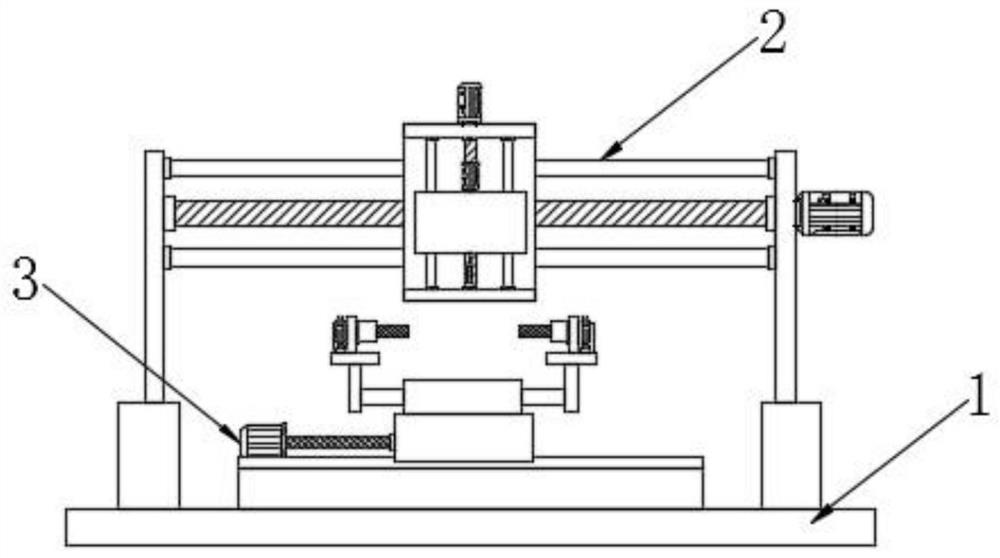
[0045] see Figure 1-10 , the present invention provides a technical solution:

[0046] A gear processing and grinding equipment, including a workbench 1, a grinding mechanism 2 and a clamping mechanism 3 are provided on the upper surface of the workbench 1, the grinding mechanism 2 includes two symmetrically distributed first support plates 201, two first support plates 201 are respectively fixed on both sides of the upper surface of the workbench 1, and the fron...


PUM


Abstract

The invention discloses gear machining and grinding equipment and an operation method thereof. The gear machining and grinding equipment comprises a workbench, a grinding mechanism and a clamping mechanism are arranged on the upper surface of the workbench, the grinding mechanism comprises two symmetrically-distributed first supporting plates, and the two first supporting plates are fixed to the two sides of the upper surface of the workbench correspondingly. First fixing seats which are symmetrically distributed are fixed to the front ends and the rear ends of the sides, away from each other, of the two first supporting plates, and first sliding rods which are symmetrically distributed up and down are fixed between the two first fixing seats. Through the arrangement of the grinding mechanism, a grinding roller is driven to freely move in the horizontal direction and the vertical direction, the movement modes are diversified, the grinding roller can move to the position of a to-be-ground gear to conduct grinding operation on the gear, no dead angle exists in grinding, the grinding efficiency is improved, and the grinding effect is improved. Through cooperation of a movable rack and a rotating gear, the to-be-ground gear is driven to rotate, so that no dead angle exists in grinding , the grinding efficiency is improved, and the grinding effect is improved.

Description

technical field [0001] The invention relates to the technical field of gear processing, in particular to gear processing and grinding equipment and an operating method thereof. Background technique [0002] A gear is a mechanical element with teeth on the rim that can continuously mesh to transmit motion and power. The application of gears in transmission has appeared very early. It appears that with the development of production, the stability of gear operation has been paid attention to, and the gear needs to be polished after production. [0003] The existing gear processing and grinding equipment has a single movement mode of the grinding roller, which limits the movement range of the grinding roller, resulting in low grinding integrity and dead angles in grinding; the existing gear processing and grinding equipment has low grinding efficiency. The grinding effect is not good; the existing gear processing and grinding equipment lacks the clamping and positioning of the ...

Claims


Application Information

Patent Timeline
Patent Type & Authority Applications(China)
IPC IPC(8): B24B19/00B24B41/06B24B47/00B24B47/12B24B47/20B24B47/22
CPCB24B19/00B24B41/061B24B47/00B24B47/12B24B47/20B24B47/22
Inventor 程金东许道益江立权陈克勤洪向明周勇刚胡建国汪宜雄程春利胡斌洪洲吴向辉冯一孝江子杰柯俊
Owner 安徽省小小科技股份有限公司
Why Eureka
Eureka Blog
Learn More