Electroencephalogram examination operation trolley
A technology for checking operation and electroencephalogram, which is applied in medical science, sensors, surgery, etc. It can solve the problems of inconvenient access to functional parts, reduce use efficiency, increase electrodes, etc., reduce the possibility of wiring misalignment, and reduce electrode pollution risk, the effect of improving wiring efficiency
- Summary
- Abstract
- Description
- Claims
- Application Information
AI Technical Summary
Problems solved by technology
Method used
Image
Examples
Embodiment 1
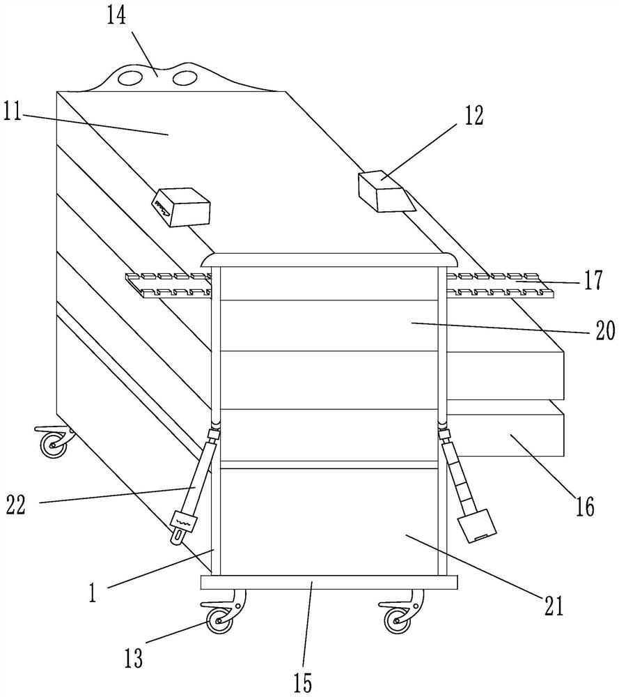
[0027] like figure 1 As shown, an EEG examination operation cart includes a car body 1, an operating table 11 is provided on the upper side of the car body 1, and an adhesive tape cutter 12 is provided on the operating table 11. The adhesive tape cutter 12 includes a sawtooth bar at the outer end, and the adhesive tape is cut through the sawtooth bar. The lower side of the car body 1 is provided with movable casters 13, the car body 1 is provided with a handlebar 14, the handlebar 14 is located outside the operating table 11 at the rear end of the car body 1, and the upper and lower ends of the front end of the car body 1 are covered with anti-collision wheels respectively. sponge 15. The car body 1 is provided with two side-opening drawers 16 adjacent up and down, and the two side-opening drawers 16 can be used to place conductive paste, abrasive cream, dry cotton swabs, adhesive tape, latex gloves, disposable Gloves, spatulas and disposable hats, etc., the car body 1 is pr...
Embodiment 2
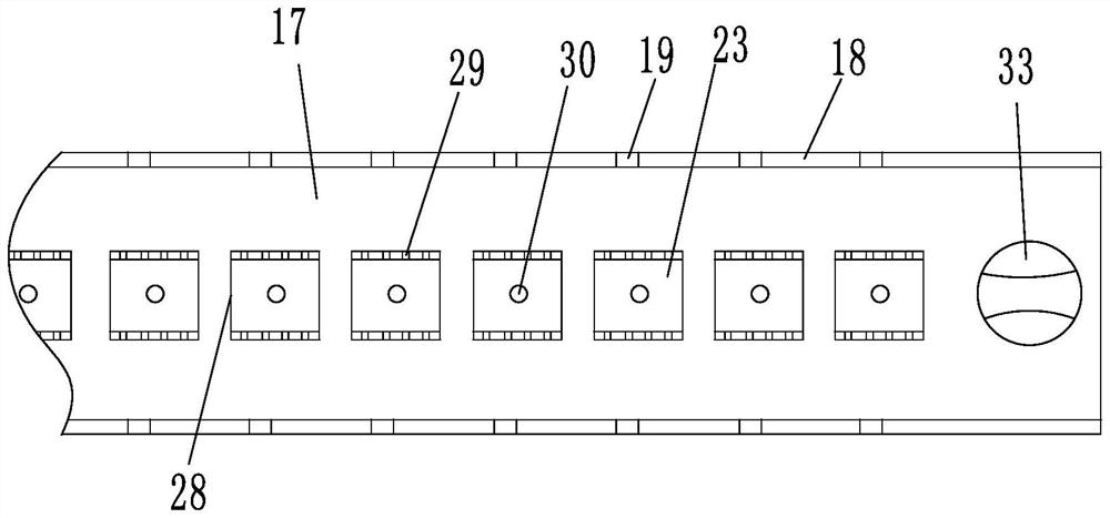
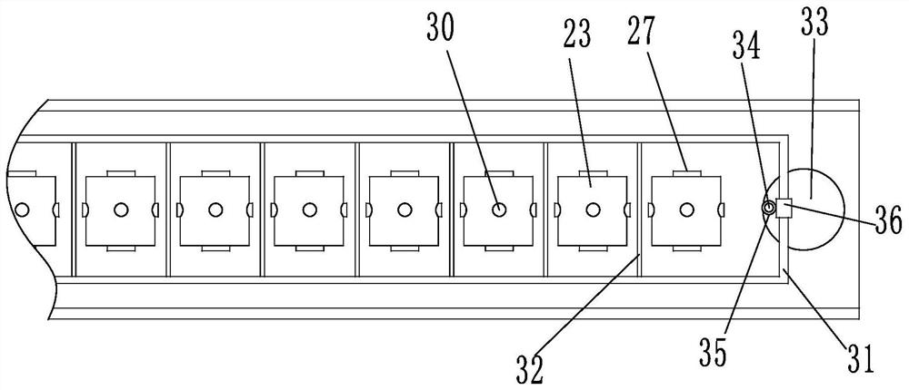
[0029] An EEG examination operating vehicle such as figure 2 and image 3As shown, the difference between Embodiment 2 and Embodiment 1 is that: the lower side of the electrode wire placing splint 17 is rotated to be provided with a take-up wheel 23, and the lower end of the electrode wire placing splint 17 is provided with a riser 27, the riser 27 and the take-up wheel 23 are connected by bearing rotation. The electrode wire placement splint 17 is provided with a take-up port 28 matching the take-up wheel 23, and the edge of the take-up port 28 is provided with four convex teeth 29 arranged at intervals, and the middle part of the take-up wheel 23 is provided with four winding lines. The limit posts 30 are arranged in an array of rings 35 on the axis of the wheel 23 . The lower side of the electrode wire placing splint 17 is provided with a limit frame 31 which is slidably arranged, and a limit rod 32 matching each take-up wheel 23 is arranged on the limit frame 31 . The ...
Embodiment 3
[0031] An electroencephalogram examination operation car, as shown in Figure 4 and Figure 5 As shown, the difference between embodiment 3 and embodiment 2 is that: the two ends of the take-up wheel 23 are respectively provided with a take-up shaft 24, the lower end of the take-up plate is provided with a riser 27, and the riser 27 is provided with a matching take-up shaft The chute 25 of 24, the end portion of take-up shaft 24 is provided with transmission gear 26 on the other side of riser 27. The limiting frame 31 is only provided with a limiting rod 32 that cooperates with the outermost take-up pulley 23 . When the limit frame 31 slides, it will drive the take-up pulley 23 to slide along the chute 25. When the adjacent take-up pulley 23 is pressed by the limit frame 31, the transmission gears 26 on it will mesh with each other, and then retreat to open the limit Frame 31, all the take-up wheels 23 can rotate synchronously, so as to realize the synchronous winding of the w...
PUM
 Abstract
Description
Claims
Application Information
 - R&D
- Intellectual Property
- Life Sciences
- Materials
- Tech Scout
- Unparalleled Data Quality
- Higher Quality Content
- 60% Fewer Hallucinations
Browse by: Latest US Patents, China's latest patents, Technical Efficacy Thesaurus, Application Domain, Technology Topic, Popular Technical Reports.
© 2025 PatSnap. All rights reserved.Legal|Privacy policy|Modern Slavery Act Transparency Statement|Sitemap|About US| Contact US: help@patsnap.com


